Development agenda in universAAL
Development agenda in universAAL - DEPRECATED !!
WARNING: this page is outdated. The content is split up into different pages, one for each protocol. Please refer to Home for the latest content.
The development agenda of LDDI EG follows the layer division we adopted for the architecture. The first basic step is to populate the Access Layer with a set of drivers enabling the management of the most popular sensor networks.
- For the Home Building Automation domain, we decided to provide a solution for the integration of KNX, the most popular HBA standard in Europe. As a basis the existing KnxNetworkdriver package from DOG2 project http://sourceforge.net/projects/domoticdog/ is used. Testing facilities for KNX integration are available since several Living Labs from partners participating in universAAL project have KNX installations.
- The ZigBee4OSGi project is taken from the Persona project (hosted now on AALOA homepagehttp://zb4osgi.aaloa.org/) and refined within universAAL. This project covers the Zigbee HomeAutomation profile.
- Furthermore we focus on technology selected by the Continua Healthcare Alliance for integration of personal health devices. The Continua Design Guidelines follow the ISO/IEEE standard family 11073, using mainly Bluetooth and ZigBee for data transmisstion. Thanks to the Antidote project http://oss.signove.com/index.php/Antidote:_IEEE_11073-20601_Library we can use an existing software stack for those devices on the access layer.
- Drivers for other emergent technologies will be added, beginning from those ones that require less integration effort.
- The ZB4OSGi project already provides such capabilities as far as Zigbee protocol is concerned.
- Regarding KNX devices we plan to use a general model for device abstraction, namely the ISO/IEEE standard 11073-10471 - Independent Living Activity Hub, proposed by the Continua Healthcare Alliance.
- Similarly for Continua-certified devices like Blood Pressure Monitor and Weighing Scale we use corresponding specifications ISO/IEEE standard 11073-10407 and ISO/IEEE standard 11073-10415.
The development of the Integration Layer deals with integration of the selected technologies with the components of the universAAL architecture. To this end, bundles named exporters will be in charge of registering the discovered devices with the universAAL buses. It is reasonable to have one of such exporters for each technology.
In the following chapters all software components are presented. For better readability and understandability they are grouped by technologies, e.g. KNX related components, ZigBee related components, and so on.
This is the bundle suite for interaction with KNX sensor networks. The suite includes the KNX message protocol and provides monitoring and control features for KNX devices (sensors/actuators). The three-layer design is implemented in a way to give flexibility to the developer wether to use the abstraction layer component, or simply bridge directly from access to integration layer. The ISO/IEEE 11073-10471 standard (Independent Living Activity Hub) is examplarily used in the abstraction layer to provide a common model for various input sensors, also from other sensor technologies than KNX. Incoming sensor events are converted to context events in the integration layer and are published on the uAAL context bus.
| Artifact: KNX network driver | |
|---|---|
| Maven artefact | org.universAAL.lddi / lddi.knx.networkdriver |
| OSGi Composite bundle | scan-composite:mvn:org.universAAL.lddi/lddi.knx.networkdriver/x.y.0/composite |
| SVN Address | <svn>/lddi/trunk/lddi.knx.networkdriver |
| Continuous Integration | <ci-lddi>/org.universAAL.lddi$lddi.knx.networkdriver |
| Javadoc | <ci-lddi>/org.universAAL.lddi$lddi.knx.networkdriver/javadoc |
| Maven Release Repository | <maven-release-lddi>/lddi.knx.networkdriver |
| Maven Snapshot Repository | <maven-snapshots-lddi>/lddi.knx.networkdriver |
| Reports | D2.3C(III) ?? |
| Design | http://forge.universaal.org/wiki/KNX Networkdriver |
| Reference | http://forge.universaal.org/wiki/KNX Networkdriver |
| Artifact: KNX Device Manager | |
|---|---|
| Maven artefact | org.universAAL.lddi / lddi.knx.devicemanager |
| OSGi Composite bundle | scan-composite:mvn:org.universAAL.lddi/lddi.knx.devicemanager/x.y.0/composite |
| SVN Address | <svn>/lddi/trunk/lddi.knx.devicemanager |
| Continuous Integration | <ci-lddi>/org.universAAL.lddi$lddi.knx.devicemanager |
| Javadoc | <ci-lddi>/org.universAAL.lddi$lddi.knx.devicemanager/javadoc |
| Maven Release Repository | <maven-release-lddi>/lddi.knx.devicemanager |
| Maven Snapshot Repository | <maven-snapshots-lddi>/lddi.knx.devicemanager |
| Reports | D2.3C(III) ?? |
| Design | http://forge.universaal.org/wiki/KNX Devicemanager |
| Reference | http://forge.universaal.org/wiki/KNX Devicemanager |
| Artifact: KNX Library | |
|---|---|
| Maven artefact | org.universAAL.lddi / lddi.knx.library |
| OSGi Composite bundle | scan-composite:mvn:org.universAAL.lddi/lddi.knx.library/x.y.0/composite |
| SVN Address | <svn>/lddi/trunk/lddi.knx.library |
| Continuous Integration | <ci-lddi>/org.universAAL.lddi$lddi.knx.library |
| Javadoc | <ci-lddi>/org.universAAL.lddi$lddi.knx.library/javadoc |
| Maven Release Repository | <maven-release-lddi>/lddi.knx.library |
| Maven Snapshot Repository | <maven-snapshots-lddi>/lddi.knx.library |
| Reports | D2.3C(III) ?? |
| Design | http://forge.universaal.org/wiki/KNX Devicelibrary |
| Reference | http://forge.universaal.org/wiki/KNX Devicelibrary |
| Artifact: KNX Datapoint1 Refinement Driver ISO 11073 | |
|---|---|
| Maven artefact | org.universAAL.lddi / lddi.knx.dpt1refinementdriver.iso11073 |
| OSGi Composite bundle | scan-composite:mvn:org.universAAL.lddi/lddi.knx.dpt1refinementdriver.iso11073/x.y.0/composite |
| SVN Address | <svn>/lddi/trunk/lddi.knx.dpt1refinementdriver.iso11073 |
| Continuous Integration | <ci-lddi>/org.universAAL.lddi$lddi.knx.dpt1refinementdriver.iso11073 |
| Javadoc | <ci-lddi>/org.universAAL.lddi$lddi.knx.dpt1refinementdriver.iso11073/javadoc |
| Maven Release Repository | <maven-release-lddi>/lddi.knx.dpt1refinementdriver.iso11073 |
| Maven Snapshot Repository | <maven-snapshots-lddi>/lddi.knx.dpt1refinementdriver.iso11073 |
| Reports | D2.3C(III) ?? |
| Design | http://forge.universaal.org/wiki/KNX DPT1 Refinementdriver ISO11073 |
| Reference | http://forge.universaal.org/wiki/KNX DPT1 Refinementdriver ISO11073 |
| Artifact: ISO 11073 Library | |
|---|---|
| Maven artefact | org.universAAL.lddi / lddi.iso11073.library |
| OSGi Composite bundle | scan-composite:mvn:org.universAAL.lddi/lddi.iso11073.library/x.y.0/composite |
| SVN Address | <svn>/lddi/trunk/lddi.iso11073.library |
| Continuous Integration | <ci-lddi>/org.universAAL.lddi$lddi.iso11073.library |
| Javadoc | <ci-lddi>/org.universAAL.lddi$lddi.iso11073.library/javadoc |
| Maven Release Repository | <maven-release-lddi>/lddi.iso11073.library |
| Maven Snapshot Repository | <maven-snapshots-lddi>/lddi.iso11073.library |
| Reports | D2.3C(III) ?? |
| Design | http://forge.universaal.org/wiki/KNX ISO11073 Library |
| Reference | http://forge.universaal.org/wiki/KNX ISO11073 Library |
| Artifact: Hardware Exporter ActivityHub | |
|---|---|
| Maven artefact | org.universAAL.lddi / lddi.hw.exporter.activityhub |
| OSGi Composite bundle | scan-composite:mvn:org.universAAL.lddi/lddi.hw.exporter.activityhub/x.y.0/composite |
| SVN Address | <svn>/lddi/trunk/lddi.hw.exporter.activityhub |
| Continuous Integration | <ci-lddi>/org.universAAL.lddi$lddi.hw.exporter.activityhub |
| Javadoc | <ci-lddi>/org.universAAL.lddi$lddi.hw.exporter.activityhub/javadoc |
| Maven Release Repository | <maven-release-lddi>/lddi.hw.exporter.activityhub |
| Maven Snapshot Repository | <maven-snapshots-lddi>/lddi.hw.exporter.activityhub |
| Reports | D2.3C(III) ?? |
| Design | http://forge.universaal.org/wiki/KNX ActivityHub Exporter |
| Reference | http://forge.universaal.org/wiki/KNX ActivityHub Exporter |
| Artifact: KNX Exporter | |
|---|---|
| Maven artefact | org.universAAL.lddi / lddi.knx.exporter |
| OSGi Composite bundle | scan-composite:mvn:org.universAAL.lddi/lddi.knx.exporter/x.y.0/composite |
| SVN Address | <svn>/lddi/trunk/lddi.knx.exporter |
| Continuous Integration | <ci-lddi>/org.universAAL.lddi$lddi.knx.exporter |
| Javadoc | <ci-lddi>/org.universAAL.lddi$lddi.knx.exporter/javadoc |
| Maven Release Repository | <maven-release-lddi>/lddi.knx.exporter |
| Maven Snapshot Repository | <maven-snapshots-lddi>/lddi.knx.exporter |
| Reports | D2.3C(III) ?? |
| Design | http://forge.universaal.org/wiki/KNX_Exporter |
| Reference | http://forge.universaal.org/wiki/KNX_Exporter |
- See this building block requirements.
The design for integration of KNX home automation (HA) components is exemplarily developed in universAAL for other HA sensor technologies and follows three characteristics:
1) LDDI uses the SAIL three-tier architecture. There are clear interfaces between access, abstraction and integration layer by using the OSGi Device Access Specification (OSGi DAS). This enforces the components to be exchangeable (e.g. usage of different drivers for devices). This approach follows also the reviewers recommendation to have standardized APIs.
2) KNX integration design provides a common standardized abstraction model for sensor hardware (ISO 11073-10471) to enforce interoperability. Integration of personal health devices follow specifications of the same Standards family (ISO 11073), as proposed by the Continua Healthcare Alliance. (full name of the standard: CEN ISO/IEEE 11073 Health informatics - Medical / health device communication standards -- Part 10471: Device specialization: Independent living activity hub)
3) KNX integration design uses the OSGi Device Access Specification for management of devices and drivers. Existing software projects are used (Apache Felix DeviceAccesshttp://svn.apache.org/repos/asf/felix/trunk/deviceaccess/) which implement the matchmaking process for devices and drivers registered on the OSGi registry. This is a standardized API within the OSGi framework which give developers clear guidelines to develop additional device drivers for the universAAL platform.
KNX components are not aware of the ISO 11073 standard. No KNX components exist that implement an so called ISO Agent. This design tries to integrate non-ISO11073-aware sensor technologies. Besides KNX there are other sensor technologies that can be integrated on the uAAL node in the same way.
The current design does not foresee fully Agent-Manager communication from the base standard ISO 11073-20601, because this would be a massive overhead with little benefit for HA component integration. But, by following this design, it will be easier to integrate future products which cover this standard (available products are listed on the Continua homepage http://www.continuaalliance.org/products/product-showcase). Only the nomenclature (domain model and notation) will be used, which is an essential component in the abstraction layer to enable interoperability between different HA technologies.
ISO 11073 Domain Information Model consists definitions of:
- Sensortypes
- Event/Messagetypes
- Locations
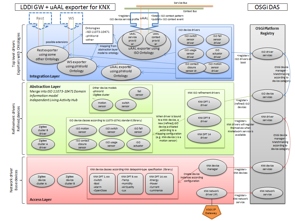
Components in terms of Maven artifacts/OSGi bundles. Not all components are bound to the uAAL middleware. In fact, only the exporter components interface the uAAL middleware and has dependencies to middleware artifacts. All maven components have Group Id: org.universAAL.lddi
'''lddi.knx.networkdriver (Access Layer)''': Establishes connection to the physical KNX/IP gateway by binding to an UDP Multicast Channel.
'''lddi.knx.devicemanager (Access Layer)''': Manages virtual KNX devices in the Access Layer.
'''lddi.knx.devicelibrary (used by components in the Access and Abstraction Layer)''': Provides class models, utils and interfaces for KNX development.
'''lddi.knx.dpt1refinementdriver.iso11073 (Abstraction Layer)''': Refinemend of KNX device (datapoint type 1.*) to ActivityHub device.
'''lddi.iso11073.library (used by components in the Abstraction and Integration Layer)''': ISO11073-10471 device model, and interfaces (API definition).
'''lddi.hw.exporter.activityhub (Integration Layer)''': Implements OSGi drivers for all ActivityHub devices (ISO 11073-10471).
As GPL and LGPL is not compatible with Apache License we try to avoid any software under these licenses as far as possible (e.g. Calimero KNX Library).
The DOG2 project is published under Apache License 2.0 on http://domoticdog.sourceforge.net/ Source code in knx.networkdriver and knx.drivers is taken from this project and adapted.
There was no KNX related code from other input projects available.
- Lead: AIT
| Plan | Description | Status |
|---|---|---|
| M12 | Split contents into separate artifacts per domain if appropriate. | done |
| M12 | Install and configure the artifact with the available platform for uaal. | done |
| M13 | Perform tests and measure performance of components using it. | done |
| M14 | Identify missing requirements, concepts and properties and implement the most urgent/mandatory ones. | done |
| M15 | Perform tests and measure performance of components using it. | done |
| M15 | Complete the missing documentation and finalize the integration with the final components (if needed). | done |
| M15 | Decide about which location ontology to use in universAAL. | done |
| M16 | Complete the modularization task for all parts of the PERSONA artefacts casf.ont, casf.ont.ext. | done |
| M21 | Adapt the existing ontologies to the changes planned by the middleware group for mw.data.representation, improve them (e.g., add the ‘Service’ classes), and complete their documentation. | ongoing |
| M27 | Continuously add new ontologies as need arises. | ongoing |
Continua Health Alliance has selected the ISO/IEEE Std 11073-20601 Personal Health Device Communication protocol for the optimized exchange of information in the PAN (Person Area Network) and LAN (Local Area Network) Interface, respectively between personal devices (e.g., sensors) and application hosting devices (e.g., computer, smartphone). The Continua Design Guidelines (version October 1, 2010) give detailed instructions how the standard should be applied for selected devices through different communication channels (Bluetooth, USB and ZigBee).
A detailed description of the relevant standard documents can be found here ISO 11073 standards family
Based on these specifications the following design concepts have been developed.
The spectrum of specified sensor types in the Independent Living Activity Hub specification (ISO 11073/Part 10471) is wide. Not all of them are "simple" sensors, e.g. Property Exit Sensor, Usage Sensor. Regarding Fall Sensor and Medication Dispenser, there exist several realizations not always consisting of one simple sensor but a conglomerate of several sensors.
For this reason, the Agent should not only map real sensors to those specified in the standard, but moreover aggregate and pre-process data from real sensors and create "virtual" sensors according to the 10471 specification. In the Continua Design Guidelines 2011 there are terms defined for both setups: Sensor-LAN and Sharing-LAN. The scope of Sensor-LAN are sensor devices having an ISO Agent integrated, talking directly to an ISO Manager; where else Sharing-LAN defines a setup where several (non ISO 11073-konform) sensor devices are connected to an intermediate computing device, which aggregates and pre-processes sensor data and transfers to an ISO Manager.
Standard-conform sensor types can be created in two ways:
- Elementary sensor types can be directly mapped to and created from real sensors (examples for sensor events: contact-opened, switch-on, high-temperature-detected)
- Complex sensor types have to be created from aggregated and pre-processed data coming from simple sensors by the agent to detect certain situations (examples of standard-conform virtually created events: occupant-exit-property, exit-door-left-open, expected-use-start-violation, absence-violation)
- to detect if an occupant left the property it might be necessary to combine information from several simple sensors and/or time constraints.
- to detect if a person has not started an activity he/she usually starts every day at this time, the agent have to have knowledge about the users behavior and daily activities.
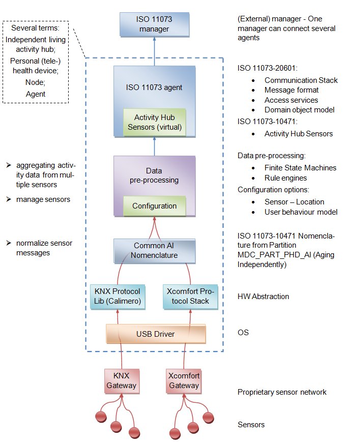
Such an Agent (like in the example concept above) needs a certain amount of processing and storage capabilities. PC-based research prototypes already exist in the size of Mini-ITX cases. An Independent Living Activity Hub Agent belongs to the environment due to the connection of home automation sensors. Therefore, the size of the Agent device is not that critical as for wearable devices. The Agent device can be placed suitably in the given environment.
This specification (Doc. 0755360r15) provides standard interfaces and device descriptions to allow inter-operability among ZigBee devices produced by various manufacturers of health care products. The specification adds restrictions at network and application level by changing the default setting of some conventional parameters, however the ZHC profile reuses, like the home automation profile, different clusters already defined in the Zigbee Cluster Library (ZCL).
Zigbee definitions:
-
Cluster:
A collection of related attributes and commands, which together define a communications interface between two devices.
The devices implement server and client sides of the interface respectively. -
Attribute:
A data entity which represents a physical quantity or state. This data is communicated to other devices using commands. -
Device Description:
A collection of clusters and associated functionality implemented on a ZigBee endpoint.
Device descriptions are defined in the scope of an application profile.
Clusters of particular relevance are the Generic Tunnel and 11073 Protocol Tunnel belonging to the Protocol Interfaces functional domain. They are used to be compliant to the ISO 11073 family standards.
Finally, the Voice over Zigbee cluster of the Telecommunications functional domain is used mainly in scenarios where the user needs to be in touch with remote operators for some emergency.
Notice that the last two clusters are not included in the ZCL specification yet. Every device belonging to the ZHC profile must implement the following clusters:
ZHC Device Mandatory Clusters
- Basic: used to hold read-only information of the device (e.g. model, manufacturer name, etc.)
- Identify: used to put the device in identification mode, in which a device uses for example a sound or blinking light to indicate to an observer where it is.
- Generic Tunnel: a set of attributes and commands needed to tunnel any protocol
- 11073 Protocol Tunnel: for tunneling data conforming to the IEEE 11073 protocol
The real description of ZHC devices is delegated to the IEEE Health informatics standard to which each ZigBee device is aligned: ISO/IEEE P11073-10404, ISO/IEEE P11073-10407, ISO/IEEE P11073-10408, ISO/IEEE P11073-10415, ISO/IEEE P11073-10417, ISO/IEEE P11073-10419, ISO/IEEE P11073-10421, ISO/IEEE P11073-10441, ISO/IEEE P11073-10442, ISO/IEEE P11073-10471, ISO/IEEE P11073-10472.
The 11073 Protocol Tunnel is the major cluster used to communicate according the above protocols. The commands provided from this cluster are:
- Transfer APDU: its payload is a byte array of variable length representing the Application Protocol Data Unit of the ISO 11073 standard. It is the only mandatory command.
- Connect Request: it specifies the IEEE address target and endpoint of the Data Management device transmitting the tunneled data
- Disconnect request: to terminate the tunneling
- Connection Status Notification: generated by the agent device for connection status change
-
Data Management
- Data Collection Unit
-
Multifunction
- Generic Multifunction Healthcare Device
-
Disease Management
- Pulse Oximeter
- ECG
- Blood Pressure Monitor
- Thermometer
- Weight Scale
- Glucose Meter
- International normalized ratio (INR)
- Insulin Pump
- Peak Flow Monitor
-
Health and Fitness
- Cardiovascular fitness and activity monitor
- Strength fitness equipment
- Physical Activity Monitor
- Step counter
-
Aging Independently
- Independent Living Activity Hub (ILAH)
- Adherence Monitor
- Fall Sensor
- PERS Sensor
- Smoke Sensor
- CO Sensor
- Water Sensor
- Gas Sensor
- Motion Sensor
- Property Exit Sensor
- Enuresis Sensor
- Contact Closure Sensor
- Usage Sensor
- Switch Use Sensor
- Dosage Sensor
- Temperature Sensor
The main components are provided by the ZB4OSGi project. The integration of the ZigBee protocol with the OSGi platform is of general interest for many application domains and its development will be separated from the specific artifacts adapted for the universAAL projects. The LDDI SVN repository is linked with the ZB4OSGi repository so that development, building and testing of ZB4OSGi components can be easily shared with universAAL specific roadmap.
Main artifact set
-
Base Driver API
- org.aaloa.zb4osgi.zigbee.basedriver.api - Version: 0.6.0-SNAPSHOT
-
Base Driver
- org.aaloa.zb4osgi.zigbee.basedriver - Version: 0.7.0-SNAPSHOT
-
CC2480 Data Link
- org.aaloa.zb4osgi.zigbee.cc2480.datalink - Version: 0.7.0-SNAPSHOT
-
Dongle API
- org.aaloa.zb4osgi.zigbee.dongle.api - Version: 0.7.0-SNAPSHOT
-
Home Automation Profile
- org.aaloa.zb4osgi.zigbee.ha.driver - Version: 0.7.0-SNAPSHOT
-
ZigBee Cluster Library
- org.aaloa.zb4osgi.zigbee.zcl.library - Version: 0.8.0-SNAPSHOT
-
ZigBee Export for uAAL
- hw.exporter.zigbee.ha - Version: 0.1.0-SNAPSHOT
The task of configuring devices and networks to achieve the needs of the specific installation is known as commissioning. There are a wide range of tasks around the commissioning:
Preliminary steps
- Survey of the radio environment
- Survey of the physical environment
- Placement of devices
- Configurations of parameters
- Application binding
- Optimization of network
- Testing and verification of correct operation
Membership
Devices included (excluded) from a specific network
Group and Bindings
How devices are logically connected to each other, or belong in groups where different logical connections are required
Application
Application-specific settings to be set
Restart Device Request It is sent by a tool (or a device, maybe a gateway for remote commissioning) instructing a device to restart with a specific set of attributes (SAS – startup attribute set)
- Startup control
- EPID of the network (globally unique network identifier)
- Channel mask
- Security information
- restore default configurations
Save Startup Parameters Request
- it allows for the current attribute set to be stored under a given index in a non-volatile way on ZigBee node (max 256 sets)
- it allows to restore one of the stored configurations
It is a suite of standard commands to assist commissioning:
- all necessary commands to deliver binding and group commissioning
- other management commands such as examining network and devices; remote control for «Permit Join» and «Leave» commands
- others …
- it defines the group
- for the commissioning of all devices belonging to the same group
- it assigns the binding to all devices in the group
Two simple use-cases describe how it is possible to exploit the commissioning:
Use Case 1
- A PC with a ZigBee Network Controller joins an existing ZigBee Network
- The commissioning tool discovers the devices in the network
- Establishing new bindings and group relationships
- verifying correct devices working
- A PC with a ZigBee Network Controller create a ZigBee Network
- all devices to be commissioned are turned on
- the devices join the tool network (maybe where the tool acts as coordinator)
- establishing binding and group relationships
- devices restart with startup attribute set defined
- verifying correct devices working
The idea is to expose the tool as an OSGi bundle, so it will be executed in a OSGI container by following modular approach adopted in ZB4OSGi.
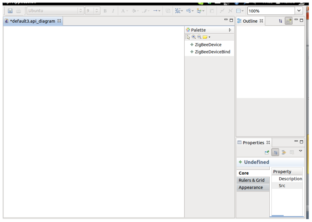
Step 1
We can start from an empty environment as shown in the next figure:
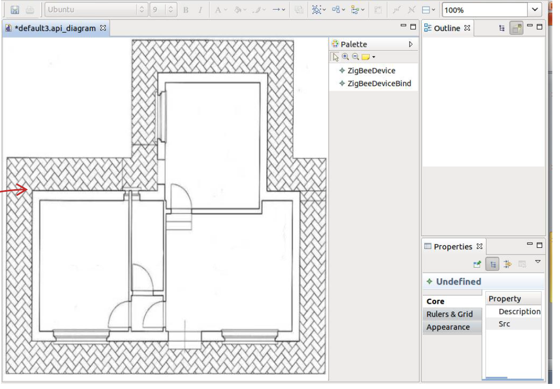
Step 2
We can add a background map to easily visualize environment representation and place ZigBee devices, as soon as they are discovered
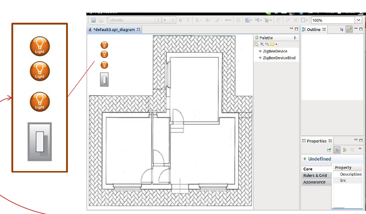
Step 3
As soon as ZigBee devices are discovered and a more specialized service is instantiated (refer to «ZigBeeDevice refinement process» in «Zigbee4OSGi stack overview» slides), the devices become available.
Responsible partner TSB:
Open source solution for integration of ISO 11073 standard compliant devices, e.g. pulse pressure monitor via Bluetooth. See http://www.continuaalliance.org/products/certified-products.html for a list of Continua Health Alliance certified products.
Andago started the Open Health Assistant project as open source, but they only made publicly available an Android application that doesn't do anything at all. It is a simple simulator, which read a value from a constant in the code. Within the code itself, there is no implementation of 11073 or Bluetooth stacks.
On the other hand, Morfeo OpenHealth project is also Android-oriented, but it is already finished, the development had stopped and there won’t be support in the future. There are several versions of the code available. Taking the more complete and updated repository as reference, the code implements a 11073 library written in Java and a HDP stack in C++ and C (based on BlueZ official Bluetooth stack from Linux). Either way, the last commit is dated on March 2011, and it is no longer supported.
Finally, we have found the Antidote project, from a Brazilian company called Signove. They made an IEEE 11073 stack in C, and it is wrapped into an Android project. There are two versions of this Android project: one coded for 2.3 “Gingerbread” (marked as obsolete and really difficult to run) and the other one uses the lastest version 4.0 “Ice Cream Sandwich” of Android OS.
The good thing about the second one is that, in addition of being published the 1st of February and it seems to be supported in the near future, Android 4.0 has native support for HDP Bluetooth profile, so the code gets simplified.
We tried to run it in a real device. For doing this, we had to flash it with a non-official Ice Cream Sandwich ROM in beta status (Bluetooth seems to work properly with the first simple tests like device syncing, though), but once we installed the Antidote applications in the device and gets synced successfully with a Continua-certified weighing scale and a blood pressure monitor, the application doesn’t retrieve the value of measurement.
After analyze the LogCat Android debug console, we observe the Bluetooth connection lasts only for two tenths of a second.
We contacted the developers and the problem seems to be related with the Linux kernel that resides on the bottom of Android OS. All ROMs we found for the device (it’s a HTC Desire Z a.k.a. Vision) are based on the 2.6.35 kernel version, and a 2.6.36 or newer it is required for getting the ETRM (Enhanced ReTransmission Mode) function of the Bluetooth stack work properly.
The simplest solution to this is to port the Bluetooth libraries from the newer kernel versions into the older, and then recompile the whole kernel and flash again the device.
Nonetheless, these problems will tend to get solved as the manufacturers build new Android devices with the newest kernel versions, or update the OS of the existing ones.
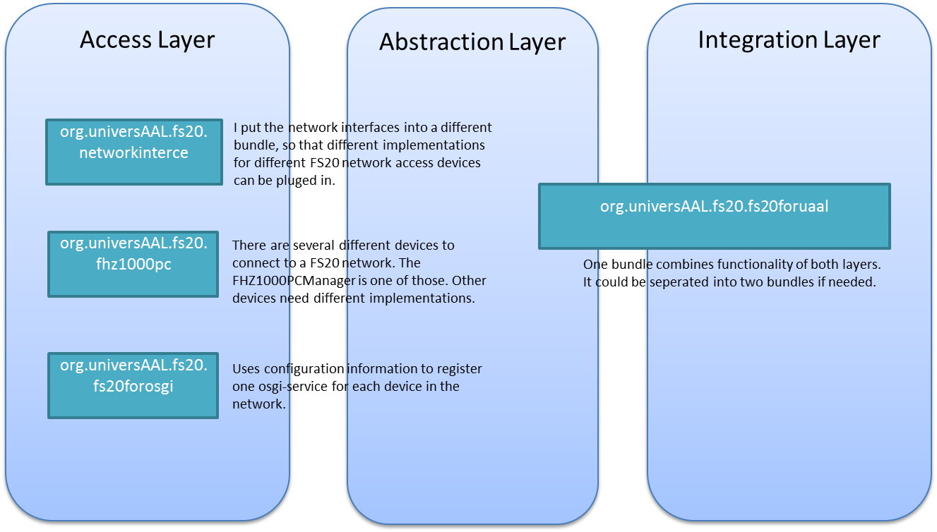
This implementation provides an integration of the FS20 protocol. In order to use the implementation you have use FS20 devices. The current implementation relies on the FHZ1000PCManager device (see http://tinyurl.com/438b272) to connect to a FS20 network. This device must be connected to the server running this implementation via USB. FHZ1000PC acts as a gateway into the FS20 network.
The FHZ1000PCManager bundle relies on a DLL (org.universAAL.fs20.fhz1000pc\lib\JD2XX.dll) that has to be put into the folder where the OSGi-framework is executed. This DLL is only working for AMD64-bit Windows. There is also another DLL for 32-bit Windows (org.universAAL.fs20.fhz1000pc\lib\JD2XX32bit.dll). To switch to 32-bit simply change the filename to JD2XX.dll and use it instead of the other one.
The integration code is currently available in the LDDI svn under the following location: http://forge.universaal.org/svn/lddi/sandboxes/peterwolf/fs20integration_Maven
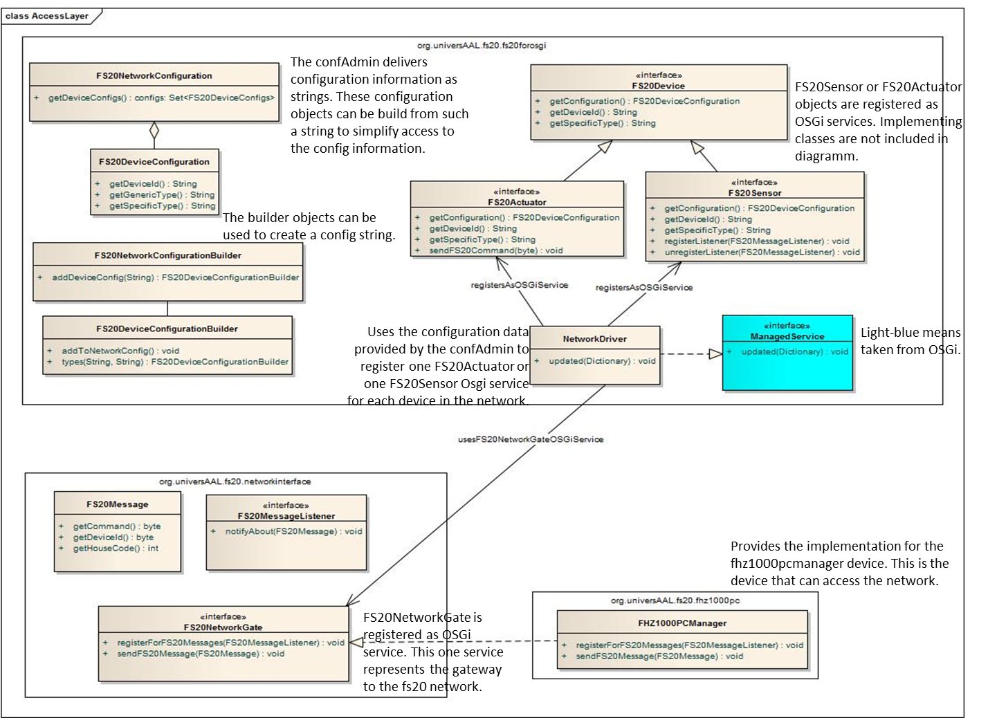
Since the FS20 protocol does not support any device discovery, the implementation must rely on a configuration procedure to get to know the network configuration (i.e. which devices are currently in the network). Configuration is handled by the ConfigurationAdmin from OSGi. The FS20NetworkDriver is the ManagedService that receives the config data. It does receive the configuration of the whole network as a string (see updated-method and Dictionary object) and, based on its content, constructs the FS20Actuator and FS20Sensor objects that are then registered at the OSGi registry (see AccessLayer description below). The FS20Actuator and FS20Sensor objects can then be used to communicate with the underlying device, i.e. register for information coming from a sensor and sending commands to a actuator.
The format of the configuration string looks currently like this:
 „device_id_1:[generic _device_type _1, specific_device_type_1] ;
  device_id_2:[generic _device_type _2, specific_device_type_2];…“

 // Example:
 "111122221111:[actuator,power_plug_actuator];442212421111:[sensor,power_plug_sensor];„
A configuration of a device consists of the device_id (FS20 housecode + FS20 device id), the generic _device_type (either sensor or actuator) and the specific_device_type (can be extended by the user; however, every FS20 device type should have a (in relation to FS20) unique specific_device_typ).
Configuration information must be injected into the FS20NetworkDriver via the configuration admin. In order to do this, some supporting classes have been provided. They can be used to create the dictionary object that is then given to the configuration admin. Depending on the configuration admin implementation that is used, you may also be able to change the network configuration based on a configuration file (most likely a java properties file as, for example, in the felix framework).
  // It is recommended to retrieve the ConfigurationAdmin via a declarative service description
  // or a service tracker
  private ConfigurationAdmin confAdmin;

  //Use FS20NetworkConfigurationBuilder to build a network configuration
  FS20NetworkConfigurationBuilder config = new FS20NetworkConfigurationBuilder();

  // Add different device sto the network
  // A configuration of a device consists of the id (FS20 housecode + FS20 device id),
  // the generic type and the specific type
  // Generic and specific types can be retrieved from static fields
  config.addDeviceConfig("111122221111").types(
        FS20Actuator.GENERIC_DEVICE_TYPE, PowerPlugActuator.ID).addToNetworkConfig();
  config.addDeviceConfig("442212421111").types(
        FS20Sensor.GENERIC_DEVICE_TYPE, PowerPlugListener.ID).addToNetworkConfig();
  config.addDeviceConfig("122134311111").types(
        FS20Sensor.GENERIC_DEVICE_TYPE, ContactSensorListener.ID).addToNetworkConfig();
  config.addDeviceConfig("223223231111").types(
        FS20Sensor.GENERIC_DEVICE_TYPE, ContactSensorListener.ID).addToNetworkConfig();

  //Create the dictionary and give it to the conf admin
  Configuration configuration =
        confAdmin.getConfiguration("fs20forosgi.FS20NetworkDriver", null);
  Dictionary props = new Hashtable();
  props.put(FS20NetworkConfiguration.FS20_NETWORK_CONFIG, config.build().toString());
  configuration.update(props);
FS20 provides a whole range of different device types. Currently, the implementation covers only a small subset of them. Consequently, it might be necessary to add additional device types to the implementation. Additionally, the configuration format currently contains only the minimal required information. However, some devices can be configured more elaborately (for example motion detectors can be configured with additional information about activation delay etc.). In the FS20 protocol this configuration is typically done at the device directly. In case you want this information also as part of the device configuration, you have to extend the configuration format, so that it can capture this additional information.
Additional device types can be added via modification of the fs20foruaal bundle. To do this, first, you have to introduce a new device type interface into package org.universAAL.fs20.fs20foruaal.devicetypes. The new device type interface must either extend SensorListener or ActuatorProxy (see examples below).
package org.universAAL.fs20.fs20foruaal.devicetypes;

/**
 * Represents a contact sensor that is usually used to detect the opening and
 * closing of windows and doors.
 */
public interface ContactSensorListener extends SensorListener {

    /** The specific device type of the sensor */
    public static final String ID = "contact_sensor";

    /** Called when the sensor has got contact */
    public void gotContact();

    /** Called when the sensor has lost contact */
    public void lostContact();
}
package org.universAAL.fs20.fs20foruaal.devicetypes;

/**
 * Represents a power plug that can be turned on and turned off.
 */
public interface PowerPlugActuator extends ActuatorProxy {

    /** The specific device type */
    public static final String ID = "power_plug_actuator";

    /** Turns the plug on, i.e. allows the current to get through. */
    public void turnOn();

    /** Turns the plug off, i.e. stops the flow of current. */
    public void turnOff();
}
Secondly, you have to provide implementations for these newly added interfaces. In general the implementation has to bridge the gap between the FS20Actuator or FS20Sensor object, that is representing the device, and the interface description provided by you (the step before) and uAAL's ContextPublisher or ServiceCallee. One example can be seen below. You can find additional examples in the fs20foruaal bundle.
/**
 * Implementation of a ContactSensorListener that is also a uAAL
 * ContextPublisher. Incoming gotContact or lostContact events are published on
 * the uAAL Context Bus.
 */
public class ContactSensorListenerUaal extends ContextPublisher implements
    ContactSensorListener {

    private static final String LOG_PREFIX = ContactSensorListenerUaal.class
        .getCanonicalName()
        + ": ";

    private String myURI;
    private final FS20Sensor sensor;
    private FS20MessageListener listener;

    protected ContactSensorListenerUaal(BundleContext context, String uri,
        FS20Sensor sensor) {
    super(context, getProviderInfo());
    myURI = uri;
    this.sensor = sensor;
    listener = null;
    }

    /**
     * @return the context provider object needed to publish context events
     */
    public static ContextProvider getProviderInfo() {
    ContextProvider cpInfo = new ContextProvider(
        "http://aal.fzi.de/TestProvider#contactlistener");
    cpInfo.setType(ContextProviderType.gauge);
    return cpInfo;
    }

    /**
     * creates a context event and publishes it on the context bus
     */
    public void gotContact() {
    ContactSensor sensor = new ContactSensor(myURI);
    sensor.setProperty(ContactSensor.PROP_MEASURED_VALUE, Boolean.TRUE);
    ContextEvent gotContactEvent = new ContextEvent(sensor,
        ContactSensor.PROP_MEASURED_VALUE);
    System.out.println("publish event on context bus: " + gotContactEvent);
    this.publish(gotContactEvent);
    }

    /**
     * creates a context event and publishes it on the context bus
     */
    public void lostContact() {
    ContactSensor sensor = new ContactSensor(myURI);
    sensor.setProperty(ContactSensor.PROP_MEASURED_VALUE, Boolean.FALSE);
    ContextEvent gotContactEvent = new ContextEvent(sensor,
        ContactSensor.PROP_MEASURED_VALUE);
    System.out.println("publish event on context bus: " + gotContactEvent);
    this.publish(gotContactEvent);
    }

    public void communicationChannelBroken() {
    }

    /**
     * activates() registers a FS20MessageListener at the underlying FS20Sensor
     * object. Within the listeners notifyAbout-method the lostContact and
     * gotContact methods are called.
     */
    public void activate() {
    if (listener == null) {
        listener = new FS20MessageListener() {

        public void notifyAbout(FS20Message message) {
            System.out
                .println("Event received in listener: " + message);
            if (message.getCommand() == 17)
            gotContact();
            if (message.getCommand() == 0)
            lostContact();
        }
        };
        sensor.registerListener(listener);
    }
    }

    public void deactivate() {
    if (listener != null) {
        sensor.unregisterListener(listener);
        listener = null;
    }
    }
}
Thirdly, the new type must be instantiated if a sensor or actuator of such type is present in the network. To achieve this one must adapt SensorController or ActuatorControler respectively. The Example below shows the part of SensorController that is relevant. The ActuatorController code looks nearly the same. Again, additional examples can be found in the fs20foruaal bundle.
    protected void activate(final ComponentContext context) {

    // ... some code left out ...

    // check for specific device type
    if (sensor.getSpecificDeviceType().equals(ContactSensorListener.ID)) {

        // create uri for uAAL instance
        String uriFragment = "fs20:" + sensor.getSpecificDeviceType() + ":"
            + sensor.getDeviceId();

        // create the correct sensorListener object and activate it
        ContactSensorListener sensorListener = new ContactSensorListenerUaal(
            context.getBundleContext(),
            Device.URI_PREFIX + uriFragment, sensor);
        sensorListener.activate();

        // put it into managedSensors
        managedSensors.put(sensor.getDeviceId(), sensorListener);
    }

    // ... some code left out ...

    }
After this you can use the newly available specific device id (ContactSensorListener.ID) in the configuration of the network. As a result the right object should be created and do its duty.
The implementation relies on helper classes to build and parse the network configuration string. If you want to change the format you have to change these helper classes in bundle fs20forosgi package org.universAAL.fs20.fs20forosgi.interfaces: FS20NetworkConfiguration, FS20DeviceConfiguration, FS20NetworkConfigurationBuilder, FS20DeviceConfigurationBuilder. Look at the updated(Dictionary config) method of FS20NetworkDriver in package org.universAAL.fs20.fs20forosgi to see how the incoming configuration string is parsed. This is the only place in the implementation where the configuration coming from the configuration admin is accessed and translated. Here, you have to decide what you want to do with your newly introduced configuration information. If you want to put it into the FS20Actuator or FS20Sensor objects, that are created based on the configuration string (also done in this method), you have to extend the corresponding interfaces.
The FS20 Integration follows the SAIL architecture. Following SAIL ensures that you have a OSGI-compliant interface with individual addressable devices. This interface can then also be used independent of uAAL.
The picture below shows the mapping of the 4 bundles onto the 3 layer architecture of LDDI. The org.universAAL.fs20.fs20forosgi achieves the required interfaces for the access layer, i.e. each device in the network must be represented by one OSGi service. The two other bundles are internal to the access layer.
The next picture gives an overview on the access layer architecture. The class diagrams are not completely up-to-date and differ slightly from what you will find in the code base.
For more information on the configuration a test bundle is provided. It uses the Builder classes to create a configuration corresponding to a test environment at FZI.
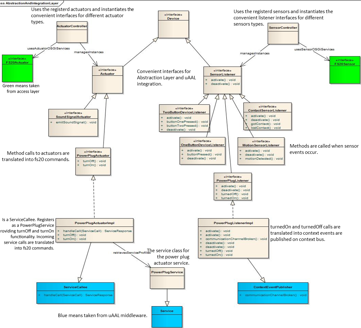
The next picture shows the abstraction and integration layer. Functionalities of both layers have been merged into one bundle. Implementations of the more convenient device interfaces (like PowerpPugActuator) that are the result of the abstraction layer, serve also as bridge to universAAL, since they also extend ServiceCallee and ContextPublisher.
-
FS20 FHZ1000PC Device
- org.universAAL.fs20.fhz1000pc - Version: 1.0.0.qualifier
-
FS20 For OSGi
- FS20_For_Osgi - Version: 1.0.0.qualifier
-
FS20 For uAAL
- FS20_For_Osgi - Version: 1.0.0.qualifier
-
FS20 Network Access Interface
- FS20_For_Osgi - Version: 1.0.0.qualifier
-
FS20 Test
- org.universAAL.fs20.test - Version: 1.0.0.qualifier
- Implementation does not use the whiteboard pattern consistently: event listeners are registered at sensor objects not at OSGi service registry
- Abstraction layer interfaces are not registered at OSGi
- currently only 3 devices are implemented on the two upper layers
The following table reports the development agenda for the LDDI expert group:
| Plan | Task | Description | Design Contribution | AIT | CNR | ITACA | TSB | Status |
|---|---|---|---|---|---|---|---|---|
| M35 | unified uAAL device model | Since a unified ontology supporting several home automation sensor technologies is hardly realizable, we will re-define the top level device.ontology in phWorld to better support these devices (sensors and actuators). Devices can be integrated using directly device- and location-ontology, or by creating a new/derived ontology supporting more technology specific details. | CNR | 1 PM | 0.1 PM | 0.5 PM | ongoing | |
| M16 | porting PERSONA ZB devices to uAAL | Integrate existing PERSONA ZigBee devices within uAAL platform | 0.25 PM | done | ||||
| M18 | consolidate ZigBee HW | Evaluate and select the available hardware (e.g. Test and integrate the CC2531 TI ZBee Dongle) | 1 PM | 0.33 PM | done | |||
| M24 | ZigBee commissioning tool | Develop the commissioning tool for final configuration of ZigBee devices deployed in an uSpace so that they work properly and according to the user preferences | 3 PM | 2 PM | ongoing | |||
| M24 | ZigBee automatic provisioning | Support for automatic download of software / drivers (from external repositories) for enabling communication with non-standard (custom) devices when they join the network. This should be activated whenever the used profile is not known a priori. It will be based on a description mechanism of ZigBee and will enable the platform to find and download the right software also for unknown devices. | AIT | 3 PM | 2 PM | ongoing | ||
| M30 | KNX integration | Implement KNX connector and provide libraries for KNX devices in OSGi. Import KNX configuration from ETS4. | CNR | 1.5 PM | 1 PM | done | ||
| M30 | IEEE 11073-10471 ActivityHub integration | Provide library for ISO 11073-10471 devices in OSGi. Export devices to uAAL buses. | 1.5 PM | 1 PM | done | |||
| M34 | Integration of Continua certified devices via Bluetooth | Integrate Bluetooth stack with HDP. Integrate open source AntiDote project or implement new ISO11073 Manager. Use D-Bus on Linux to get measurement data from Continua-devices. | 1.5 PM | 0.5 PM | ongoing |