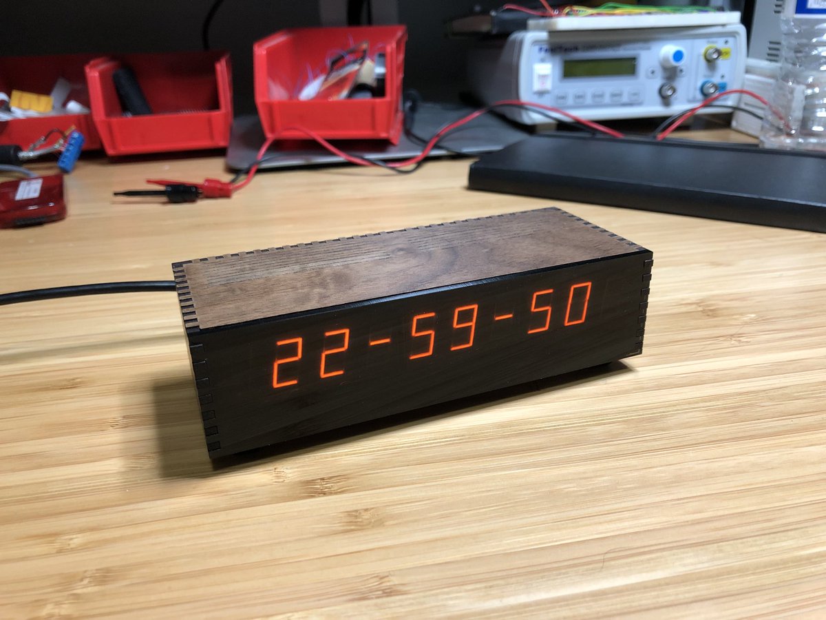
This is a digital clock that uses "Panaplex" planar gas discharge displays. Panaplex displays are basically Nixie tubes with a seven-segment cathode arrangement instead of one shaped cathode per digit. And they look awesome. The uniform orange glow and lack of gaps between segments make them much more visually appealing than LED displays.
- 10-digit display
- Sleek, buttonless enclosure made from laser-cut walnut hardwood and acrylic
- Powered from a 5V USB charger
- Coin cell battery backup keeps time when unplugged
- Two capacitive touch sensors for user input
- Highly accurate oscillator; keeps time within ±2 parts per million (about 1 minute per year)
- 12-hour or 24-hour time display with seconds
- Weekday, month, date, and year display
- Automatic calculation of weekday from month/day/year
- Automatic leap year correction up to 2099
- Automatic daylight saving time correction (US) up to 2099
- Sleep mode: display is normally blanked, and a touch displays the time for 10 seconds before fading out
- Scheduled sleep: for each day of the week, the clock can be configured to be on contiuously, in sleep, or on during one of two configurable time ranges
"Panaplex" was a trademark of Burroughs Corporation, but on the internet, the term is now used generically to describe planar gas discharge displays made by other manufacturers.
The particular modules used in my clock (the SP-35x series) were introduced by Sperry's Information Displays Division in the early 1970s. I haven't found an exact date of introduction, but they are listed in this gorgeous February 1973 Sperry Information Displays Catalog (pdf), which implies they were introduced in 1972 or earlier. Sperry's display division was acquired by Beckman later in 1973. Babcock acquired the display division from Beckman in 1984. Babcock was acquired by Microsemi in 2008.
These gas discharge displays (also called "plasma displays," though nowadays that term refers to TVs) were used extensively in aviation (as they are readable in bright sunlight) and in many pinball machines starting from the mid-1970s. They are still sold by Vishay at exorbitant prices.
I built the clock predominantly out of parts I had on hand. The electronics are constructed on four single-sided PCBs I milled with a desktop CNC machine. Here's a top view:
             Display Board
     ──────────────────────────────
 Left│                            │Right
 Wing│       ┌───────────┐        │Wing
Board│       │Logic board│        │Board
     │       └───────────┘        │
- The display board contains the Panaplex displays and the anode drive transistors
- Each "wing board" is mounted at a right angle to the display board and contains a cathode driver chip
- The logic board contains the microcontroller, real-time clock, backup battery, and high voltage power supply
Dave Jones of EEVblog has a great series of videos (part 1, part 2, part 3) where he describes how Nixie tubes can be driven with inexpensive TPIC6B595 open-drain shift registers instead of more expensive/exotic parts designed specifically for high voltage display applications. The TPIC6B595 is a cousin of the 74HC595 shift register (and also the namesake of my online handle) with 50V clamping diodes on its eight outputs.
Like Nixie tubes, Panaplex displays require a DC anode voltage of about 160-180 volts to operate. I'm using a Taylor Electronics 1363 high voltage supply module to step the 5V input voltage up to about 165-170V.
In addition to requiring a 5V supply, the TPIC6B595 also requires logic high inputs to be at least 4.2V. This meant that I would either have to
- use a microcontroller and real-time clock that could operate from a 5V supply, or
- add a 3.3V regulator and level translation circuitry between the microcontroller and the TPIC6B595s
I decided to go with the former to minimize part count. Looking through the microcontrollers I had on hand, I chose a PIC16F1508 with 256 bytes of RAM, 4K of ROM, and 18 I/O pins. The ATtiny461A was the runner-up, but it only had 15 I/O pins, and the criss-crossed VCC and GND pin arrangement would have made a single-sided board layout difficult. All the ARM chips I had on hand were 3.3V parts, so an 8-bit micro was the only option.
To strike a good balance between pin usage and part count, I ganged the digit anodes together in pairs:
   ┌─────────────┐
   │   ┌─────┐   │
┌─┬─┬─┬─┬─┬─┬─┬─┬─┬─┐
│5│4│3│2│1│1│2│3│4│5│
└─┴─┴─┴─┴─┴─┴─┴─┴─┴─┘
 │   │   └─┘   │   │
 │   └─────────┘   │
 └─────────────────┘
This arrangement only requires 5 anode drive circuits (10 transistors total and 5 I/O lines). The display is multiplexed by the microcontroller; only 2 digits are ever illuminated at a time, so we need to be able to drive 16 segments at once. For this, I used two TPIC6B595s; one to drive the cathodes of the digits on each half of the display. This led to a compact form factor where the display PCB was no larger than the displays themselves, with each TPIC6B595 on a "wing" board mounted at right angles to the display board.
My favorite real-time clock chip, the PCF2129AT, has a recommended 4.2V maximum supply voltage. Rather than push it past its specs, I Amazon Primed a SparkFun DeadOn RTC breakout board. The DS3234 is a highly accurate (±2ppm) clock, but golly gee whiz is it expensive. But, since this was a one-off, and Amazon Prime was the only way I was gonna get a DS3234 within 2 days, I figured it was OK to splurge.
The enclosure design is an homage to the wood-grain Heathkit clocks from the 1970s, like the GC-1005. After searching through my parts boxes for some nice buttons and coming up empty-handed, I decided to use capacitive touch pads for user input, which resulted in a very clean design with no protrusions.
The PIC16F1508 doesn't have any dedicated touch sensing hardware, but I stumbled upon Microchip Application Note AN1298 which describes a technique that uses the built-in analog-to-digital converter and requires no external components. I still don't fully understand how it works (capacitive touch sensing is serious black magic) but it does the job!
Microchip has another app note, AN1334, that describes a lot of great hardware and software techniques for implementing capacitive touch. By sampling the touch sensor every 64 microseconds and using the slew-rate-limiting algorithm described in that document, I was able to get considerable noise reduction.
When power is first applied, several readings are taken from the two touch sensors to establish a baseline level. It takes 512 samples of a touch sensor to establish whether it is "pressed" or not. If a certain number of those samples deviate sufficiently from the baseline value, the sensor is considered "pressed." Since the touch sensors are read one at a time, the full input state is updated at a rate of 15.26 Hz. Though this figure seems low, I haven't found any issues with responsiveness.
Timer2 drives the display multiplexing, at a rate of 4 kHz. (Each pair of digits is on for 250 microseconds). However, I ran into an issue.
I started out thinking I would strobe the digits sequentially in pairs:
. . . . 1 1 . . . .
. . . 2 . . 2 . . .
. . 3 . . . . 3 . .
. 4 . . . . . . 4 .
5 . . . . . . . . 5
. . . . 1 1 . . . .
etc.
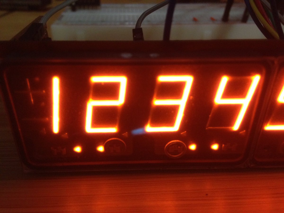
But I was noticing a strange blue discharge between neighboring digits. These blue "streamers" can appear if there is insufficient blanking time between two neighboring digits; the anode with the lower potential will act like a cathode, resulting in a visible blue glow between anodes.
(Interesting aside: where exactly are the anodes? Unlike Nixie tubes, which have visible anode grids in front of the digits, there's nothing like that to be found in Panaplex displays. Well, it turns out that the anodes are in front of the digits, but they're made of indium tin oxide, which is a transparent conductor! How cool is that?)
So, to increase the blanking time between neighboring digits without inserting additional blanking intervals, I strobe the digits in a staggered sequence:
. . . . 1 1 . . . .
. . 3 . . . . 3 . .
5 . . . . . . . . 5
. . . 2 . . 2 . . .
. 4 . . . . . . 4 .
. . . . 1 1 . . . .
etc.
(No streamers appear between the two central digits because their anodes are tied together and are always on simultaneously.)
Timer0 fires every 64 microseconds, causing a touch sensor to be sampled. After 1024 ticks of Timer0, the input state is updated and one iteration of the main loop is run. As mentioned earlier, this gives the main loop an update rate of 15.26 Hz, which is sufficient for simple animations.
The real-time clock's 1 Hz square wave output is used to tell the PIC when to fetch the new time.
I didn't want to have to manually set the weekday whenever I changed the clock's date. So Sakamoto's method is used to determine the day of the week for a given date. By restricting the year to the range 2000-2099 I eliminate the divisions by 100 and 400, which would be expensive as the PIC has no divider. The modulo-7 operation is still required, but I chose to implement it with repeated subtraction rather than use the % operator and pull in the large division routines. Plus, the weekday calculation only needs to happen when the user changes the date. The real-time clock takes care of incrementing the weekday at midnight, but has no notion of how weekdays relate to dates.
The table for automatic daylight saving time correction (for the United States only) only requires 1 byte of data per year. For the range of years from 2000-2099, the spring transition can only occur on one of 14 dates, and the fall transition can only occur on one of 13 dates. Thus, all you need to encode daylight saving time data for a year are two 4-bit indexes into a table of month/date pairs.
Since the real-time clock stores its data in binary-coded decimal format, I try to do as many internal calculations and comparisons in BCD as possible. Converting from BCD to binary representation (i.e. for doing a table lookup) is simple; (low nibble) + 10*(high nibble). The multiplication by 10 can be reduced to left-shift and add operations. Converting from binary to BCD requires division by 10, but the code never actually has to do this.
As for the code itself, it's written in C, and not something I'm particularly proud of. I haven't taken the time to split functions up into logical groups or add comments. The PIC is a nightmare for C, due to its bank-switching scheme and lack of a general-purpose stack. This makes pointer operations (especially function pointer operations) consume considerable ROM space. The 1508's enhanced mid-range architecture adds a linear addressing scheme and new instructions for indirect access/jumps, but Microchip's non-FOSS XC8 is the only compiler that takes advantage of them. The PIC backend for the open-source SDCC compiler does not seem to be under active development.
Let's call the two touch sensors on top of the clock L and R. (assuming you're looking at the clock's face.)
Normally, the clock displays the time, in the form HH-MM-SS (in 24-hour mode) or HH-MM-SS A/HH-MM-SS P (in 12-hour mode)
At the 26th second of even minutes, the display cycles to show the day of week, month and day for three seconds, then cycles to the full date in MM-DD-YYYY format for three seconds, then back to the time display.
Tap L or R to manually cycle between displays.
Hold L to enter the menu (see below).
Hold R to turn off the display. The display will fade out. Tap either L or R to resume normal operation. All timekeeping operates normally when the display is off.
The menu is accessed by holding L from the time display. Tapping L cycles through various menu items (to be explained in individual sections below):
- Sleep mode on/off/scheduled
- Set time
- Set date
- Set year
- Select 12-hour or 24-hour display
- Automatic daylight saving time correction on/off
- Time separators off/solid/flashing
- Change time separator appearance
- Change date separator appearance
- Set sleep schedule
- Done (tap
Rto exit the menu)
Hold L at any time to return to the time display. Tapping R either changes the flashing value or enters a submenu.
From the time display, hold L to enter the menu. Tap L again to advance to the "set time" prompt:
SET HH.MM
The word SET will be flashing. Tap R and the hours will flash. Tap or hold R to advance the hours. Tap L and the minutes will flash. Tap or hold R to advance the minutes. Finally, tap L one last time to store the new time and reset the seconds to 00.
At this point, SET should be flashing again. Tap L to advance to the "set date" prompt:
SET MM-DD
Tap R and the month will flash. Tap or hold R to advance the month. Tap L and the date will flash. Tap or hold R to advance the date. Tapping L one last time advances to the "set year" prompt:
YEAR YYYY
The year should be flashing. Tap or hold R to advance the year. Valid years are 2000-2099.
From the time display, hold L to enter the menu. Tap L until you arrive at the 12/24-hour prompt:
DISP. 12hr (or) DISP. 24hr
Tap R to alternate between 12-hour and 24-hour modes.
From the time display, hold L to enter the menu. Tap L until you arrive at the daylight saving time prompt:
D.S.T. AUTO (or) D.S.T. OFF
If DST is set to AUTO and the current date is currently in daylight saving time, a + will illuminate on the left side of the display.
Only US daylight saving time is supported. On the day of the spring transition, the clock will advance 01:59:59 -> 03:00:00. On the day of the fall transition, the clock will advance 01:59:59 -> 01:00:00.
Note: an ambiguous condition exists when attempting to set the time to 01:00-01:59 on the day of the fall DST transition. The clock does not know if you mean "the hour 01:xx before the transition" or "the hour 01:xx after the transition." In this situation, the clock always assumes the former.
The separators ("colons") between hours, minutes, and seconds can be set to either illuminate solidly, flash once per second, or be off entirely.
From the time display, hold L to enter the menu. Tap L until you arrive at the time separator prompt:
SEP. SOLID (or) SEP. FLASH (or) SEP. OFF
Tap R to cycle between the options.
Tap L again to advance to the time separator style prompt:
SEP.STYLE -
You have four choices of time separator:
- hyphen
- - dot
. - pseudo-colon (looks like
=) - tall pseudo-colon (top and bottom horizontal segments illuminated)
Tap R to cycle between the options.
Tap L again to advance to the date separator style prompt:
DATESEP. - (or) DATESEP. .
Tap R to select either a hyphen or dot as the separator between month, day, and year.
From the time display, hold L to enter the menu. The first item allows you to select between three modes:
SLEEP OFF: display always on 24 hours a daySLEEP ON: display normally off; touch to wake for 10 secondsSLEEP SCH.: scheduled sleep (customizable per-day asleep/awake time ranges)
Tap R to cycle between the options. Additionally, the + will illuminate if the clock is currently awake, and the - will illuminate if the clock is currently in sleep mode.
To edit the sleep schedule, tap L until you arrive at
SET SCHED.
Tap R to enter the schedule submenu:
DAYS 1 2
The selection DAYS will be flashing. Tap L to cycle between three selections:
DAYS- select a sleep schedule for each weekday1- edit Range 1 (see below)2- edit Range 2
With DAYS flashing, tap R to enter
Su. _ _ _ _ _ _ _
Each character represents a day of the week, Sunday to Saturday. Tap L to advance between days, and tap R to select an option for each day:
_- display on 24 hours a day1- display on during the hours of Range 1 and in sleep mode otherwise2- display on during the hours of Range 2 and in sleep mode otherwiseΞ- in sleep mode 24 hours a day
Hold L to return to the schedule submenu.
By selecting Range 1 or Range 2 for a given day, the clock can automatically turn the display on and enter sleep at specific times.
From the schedule submenu, tap L until either 1 or 2 is flashing, then tap R to enter the range editor.
In 24-hour mode, the range editor display looks like
1. 09--17
In 12-hour mode, the range editor display looks like
1. 9A- 5P
The first hour should be flashing. This is the time when the display should turn on. Tap or hold R to advance the on-hour.
Tap L and the second hour should be flashing. This is the time when the clock should go to sleep. Tap or hold R to advance the off-hour.
If the on-hour is later than or equal to the off-hour, an apostrophe ' will appear next to the off-hour:
1. 20-03'
This means "turn on at 8PM (20:00) and go to sleep at 3AM (03:00) the next day."
When the display is active, the clock consumes about 500 mA (2.5 watts). However, there seems to be a large inrush of current when the high voltage supply is turned on; if the power supply can't handle it, the supply voltage may drop low enough to trip the PIC's brown-out reset circuit. This manifests as a delay of about a second when touching to wake from sleep. The PIC is resetting, and the clock always goes through a touch sensor calibration cycle after a reset, which takes about one second.
A high-quality USB power adapter capable of handling at least 1A will prevent this from happening. The Apple 5W Power Adapter (model A1385) works very well. I've seen this happen with cheaper USB adapters that claim to handle 1A.
I have not measured standby current, but my estimate is a few milliamps.
Total time to project completion was about a month and a half.
Follow me on Twitter for future project updates and random electronics stuff: @txsector