Add explanation of Scan Angle Rank #41
Comments
|
There is an enormous amount of LiDAR out there where the scan angle rank (and not also the scan angle) is in local scanner coordinates, which is also nice as is allows to easily clip those parts of the LiDAR shot by the moments of the mirror movement when it was about to turn around (the less precise and unnecessarily dense parts of an oscillating mirror systems). Maybe we could use a bit of the global encoding bit mask to specify whether local or roll-compensated angles are stored. That would make it easy to fix those Exabytes of existing LAS / LAZ files that have it one way or the other (just flip the bit to the right state). |
|
@esilvia, while we're clarifying this field description (and I assume Scan Angle as well), is there existing discussion that addresses the expectations for various scanner types? Elliptical (Palmer) scanners, for example, essentially have a fixed scan angle. Artificially projecting the true look vector to the platform cross-track plane would give the incorrect impression that the scanner is oscillating below the platform through a range of angles. If these values were used for radiometric correction, as indicated by your attached discussion, the resulting values would be incorrect. I suppose the gist of this question could be summarized as whether this value is intended to represent a concept separate and distinct from elevation/declination angle between a point and the sensor. Second, is the coordinate system supposed to be with respect to the platform, or with respect to the trajectory? Finally, what value does the sign add to this field? Are there cases where the "left" side should be treated in a different manner than the "right" side? |
|
@kdamkjer can you please explain to me how a Palmer scanner has a fixed scan angle? Do you really mean that the scan angle cannot be properly recorded as a +/- cross track value as currently represented in the scan angle field? In that case, I would think the LAS WG would need to develop a new way to accurately represent the pointing vector of a palmer scanner, instead of setting it as a fixed value. |
|
@jstoker74 I think the confusion lies primarily in what information the scan angle is attempting to capture. For a Palmer scanner, the angle at which the laser pulse leaves the sensor (and similarly, the angle at which photons arrive at the sensor) is fixed and rotates about a fixed axis resulting in a conical illumination pattern (assuming a fixed platform). This means that the scanner, most likely, never looks directly nadir. The scan angle can be properly recorded as a +/- cross-track value, but what information does that convey to end-users? Encoding the scan angle in this way seems to violate the principle of least astonishment. That is, an end-user examining the scan-angle field populated according the the spec for a Palmer would probably be surprised to learn that the scanner never actually looks nadir. The pointing is no less precise at the flight-line edges than it is anywhere else in the scan pattern, because the scanner never undergoes rapid deceleration/acceleration. Of course, the scan angle doesn't actually capture the look vector for oscillating sensors either, just an approximation. Further adding to the confusion is the fact that the spec is ambiguous on whether "cross-track" is with respect to the trajectory or the platform since there is language referencing both:
If the intent of this field is to capture the off-nadir angle of the line of sight vector, then it is trivial to compute for any scanner type. Of course, if this is the intent, then the sign carries no significant meaning. If the intent, is rather, to allow clipping of less precise portions of the scan pattern from oscillating systems, why does the value need to be roll-compensated and w.r.t. the trajectory? If a line-of-sight vector is intended, why not encode as azimuth and elevation? |
|
Before we invest a lot of time in getting proper support for a Palmer scan angle it might be good to take a step back and look at how the scan angle rank field of point types 5 and lower (or the higher resolution scan angle of point types 6 or higher) is actually used. I think the main intent has been to allow clipping of less precise portions of the scan pattern from oscillating system. Since the history of the LAS Working Group discussions has been systematically deleted (my old lamenting) we will never know. I have personally seen only the following uses myself (1) remove overlap in point layers (aka "overage") between flightlines by giving preference to the points with the lowest scan angle (those that are closer or more "below" the aircraft). Although they may not be of higher quality for a Palmer scan angle system I see no obvious "better" approach to that processing step than also using the point closer to the aircraft. (2) reduce the amount of points by lessening the overlap between flightlines simply by clipping scan angles above 25 or below 25 degrees (3) pick subset of returns whose scan angles are pointing in different directions below the plane for more robust line intersection calculations (e.g. for example to recover the position from where the laser shots was fired from subsequent pairs of multi returns that were shot at a sufficiently different scan angle. (4) color the points based on their proximity to being below the aircraft's trajectory. (5) >>your use case<< For all these processing steps I do not see how a complete "Palmer angle" improves the situation. Maybe this is a case for a more precise specification of the "scan angle rank" and the "scan angle" as being a cross-track angle that is either roll-compensated or not (as per a new global encoding bit) and consider adding a new and spec-sanctioned extra byte attribute for those few folks who care about also having the along track angle of the laser beam. |
|
If I'm understanding the specification properly, then clipping according to Scan Angle or Scan Angle Rank should result in a clipped volume similar to the green region in the following images. This involves:
As @esilvia showed in #16, following this procedure results in consistent clipping volumes regardless of scanner type. Is clipping the primary intended use of this field? If we instead take the much simpler approach of projecting to the sensor reference frame (illustrated by Line "A" in the attached images) or simpler yet, just reading out scanner encoder values, we get clipping volumes as illustrated by the translucent yellow regions in the attached images. As @esilvia says in #16, this looks, "screwy," for elliptical scanners. Further, it appears to be inconsistent with the specification. It does have the advantage for oscillating scanners, though, that less precise portions of the scan can be easily removed.
The images shown above are admittedly rather ideal since the trajectory is a straight line. In reality, the computed scan angles would "lead" or "lag" any platform motion for sensors that look ahead or behind as @esilvia already mentioned. Of course, I still think that much of the confusion surrounding this field stems from the wording in the specification. For the older scan angle rank, "the angle (rounded to the nearest integer in the absolute value sense) at which the laser point was output from the laser system including the roll of the aircraft." For the newer scan angle, "represents the rotational position of the emitted laser pulse with respect to the vertical of the coordinate system of the data." Both of these phrasings make the field sound like it is supposed to be an off-nadir angle. With this understanding, adding a sign to the value is immediately confusing. Computing off-nadir angle is very straight-forward and would still permit clipping for line scanners as shown above. Of course, for elliptical scanners, the utility would probably be minimal since they have an essentially fixed off-nadir scan angle. |


|
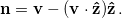
One more thought. Is there any reason that the math involved in computing this field isn't explicitly spelled out in the spec? That would surely remove any ambiguity. I believe the following procedure captures the relevant details. Given an instantaneous velocity vector for the sensor in ENU (
Thus, the unit normal to the trajectory cross-track plane (
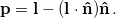
Given a look vector from the effective focal point of the sensor to the remotely sensed point (
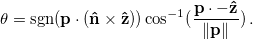
Finally, the cross-track scan angle (
To @rapidlasso's point, if remediation of existing products is desired, a Global Encoding bit can be provided that simply changes the definition of With this information, the utility of the field for various scanner types may remain debatable, but any ambiguity about how to populate the field would be removed. |


|
Apologies for my delays responding to this excellent discussion with @kdamkjer and @rapidlasso. I think the very existence of this discussion is evidence in itself that clarity is required. I have nothing to add to the excellent summary of use cases for the scan angle rank that @rapidlasso prepared. In all these cases I believe that the adoption of a cross-track nadir angle remains the most useful implementation. I disagree with @kdamkjer that this violates the Principle of Least Astonishment (POLA) for elliptical/Palmer scanners; on the contrary, because linear sensors penetrated the market long before Palmer/elliptical scanner's I'd assert that computing the cross-track nadir angle for an elliptical scanner (as RiProcess currently does, if I'm not mistaken) actually upholds the POLA because it makes datasets from elliptical scanners appear more similar to datasets from oscillating scanners and therefore can receive the same treatments. I'd agree with @kdamkjer that we'd also have to clarify whether it's cross-track relative to the sensor or trajectory. It's pretty rare that the two are significantly different, but I've seen it occur in situations of extreme "crabbing" in which the plane/sensor's orientation must be rotated off-track to correct for strong cross-track winds. The "yaw/heading" angle stored in most trajectories I've seen seems to correspond to the sensor frame, so I think it would be simplest to make the scan angle rank consistent with that implementation – that is, I would define the Scan Angle Rank as the cross-track nadir angle relative to the sensor (line A in the previous post). Regarding the sign, I see no reason not to include the left/right directionality. |
|
As for including the equation for the actual computation, I don't see a need to include that in the specification itself, but I believe it would be appropriate to include in an associated wiki page. Issue #16 was created explicitly to address the theoretical need to include other types of angles, such as the along-track component of the scan angle, as I believe they are separate, though related, issues. |
Pretty much every LAS file in the past has a signed value in the 8 bit scan angle rank field and that tradition was continued forward into the 16 bit scan angle field. Changing this now would be confusing. Most of my use cases compute the absolute value fabs(angle). But there is a use case for the scan angle. Not always the scanner is mounted to point straight down. It may have a field of view from -27 to 33 degree if there is a certain tilt in the way it is mounted. Without the sign it's impossible to do certain operations that account for this tilted mounting because it's no longer clear from which "side" around zero the returns are. |
|
Can someone from the legacy LWG confirm whether or not the Scan Angle (PDRFs 6-10) and Scan Angle Rank (PDRFs 0-5) were intended to have the same meaning? That seems to be true in practice, but I'd like confirmation of the intent. @rapidlasso @lgraham-geocue @hobu If they have the same meaning (as I believe to be true), then the only material differences would be that Scan Angle Rank is valid ±90° and has 1° resolution, while Scan Angle is valid ±180° and has 0.006° resolution. The wording between the two fields should be more similar to ensure a consistent interpretation. If they are not the same, the differences should be more clearly spelled out. |
|
Here's the language in the current R14 draft: Scan Angle Rank (PDRFs 0-5)
Scan Angle (PDRF 6-10)
|
|
yes, it was called ‘rank’ because of the low resolution.
…Sent from my iPad
On Nov 26, 2018, at 13:32, Evon Silvia <notifications@github.com<mailto:notifications@github.com>> wrote:
Can someone from the legacy LWG confirm whether or not the Scan Angle (PDRFs 6-10) and Scan Angle Rank (PDRFs 0-5) were intended to have the same meaning? That seems to be true in practice, but I'd like confirmation of the intent. @rapidlasso<https://github.com/rapidlasso> @lgraham-geocue<https://github.com/lgraham-geocue> @hobu<https://github.com/hobu>
If they have the same meaning (as I believe to be true), then the only material differences would be that Scan Angle Rank is valid ±90° and has 1° resolution, while Scan Angle is valid ±180° and has 0.006° resolution. The wording between the two fields should be more similar to ensure a consistent interpretation.
If they are not the same, the differences should be more clearly spelled out.
—
You are receiving this because you were mentioned.
Reply to this email directly, view it on GitHub<#41 (comment)>, or mute the thread<https://github.com/notifications/unsubscribe-auth/AeCJ4XoCPbVErMaB8cn4Nbi7hnm7UUGOks5uzDPJgaJpZM4QWtIk>.
|
|
Evon, digging up an old topic here. One additional factor of consideration in this entire topic is the flexibility of the LAS formats with technologies. PDRF 0-5 (and older LAS formats) have a +/- 90 degree limitation, which obviously is focused on airborne lidar. The latter PDRFs supporting +/- 180 degrees allows for full support of terrestrial and mobile applications (or airborne scanners that might have larger than a 180 degree FOV). This might be a topic worth clarifying in the definition, it is already partially visible in that scan angle rank mentions aircraft but scan angle does not. Additionally the phrasing in your example (it may have since changed) is a bit inconsistent due to the description of scan angle rank including the frame of reference (aircraft) roll, but this clarification does not exist in the scan angle definition. Thinking outside the box on adding even more capability while aiming to solve the palmer issue (and other non perpendicular scanning systems), has there ever been consideration of adding a 2nd (or 3rd) axis into the format? The first two axes would be angles cross track, and angles along track. The 3rd axis I wouldn't see being a critical measurement (unless another technology has an application for this). Having both the cross track and along track angles would allow for the true pointing angle/vector to computed rather easily. Additionally aside from palmer scanners, many of the multi-channel airborne scanners (e.g. Riegl 1560, Leica ALS80, etc) are not actually scanning exactly cross track and do actually have a forward/reverse look angle that changes across their full scan. |
|
I agree completely with @nkules and am rather surprised by the lack of response. The language of the specification for Scan Angle Rank is entirely aerocentric and we should consider it obsolete given the market dominance of mobile car based and other terrestrial LiDAR scanners. The current definition only makes sense for airborne scanners that are directed straight down (angle from nadir) and can be confusing even for the airborne case when non-perpendicular scanners (as already mentioned above) are used. In a similar vein the definition for scan angle of
has no meaning for sensors that are not aligned with the trajectory I believe that this problem will only exacerbate as new scanners enter the market. That the current standard is modern enough to address aggregate model systems but fall short in this way seems strange. Until this field is made deprecated or reworked, the LAS specification, as it currently stands, is not appropriate for mobile LiDAR use. I support @nkules suggestion of adding a second angle to the format. For a mobile LiDAR that allows 2D scanning, the one axis angle means nothing without provision of a second that would provide a pointing vector. In addition to this I would also see benefit in adding a field for the distance to the point from which the spot size and stochastic information could be derived. |
|
What have people been using the scan angle (or scan angle rank) for and how would the additional scan angles be used? In LAStools the main uses are filtering points at the edges of the swath (i.e. dropping high scan angles or keeping points with low scan angles) and deciding which set of points to keep when there is flightline overlap and only one layer of points is to cover the surveyed area (i.e. keep the points from the flight line that surveyed the area with a smaller flightline). In forestry the scan angle can be used as an additional metric for machine learning as the scan angle tends to have a significant impact on certain metrics (i.e. higher scan angles / less nadir shots have lower penetration). |
|
Scan angle rank gives the ability to consider a LiDAR point as not just a single datum but potentially give information on an entire ray (moreso if 2 angles and/or a distance are provided) as to the non-existence of obstructions. Pointing information indicates surface orientation, for aerial it can be used to obtain distance, expected beam size/shape and some statistics without having to delve into waveform data. Filtering on high angles allows to highlight points more likely to look under structures, e.g. culverts for flood monitoring. For aerial flight at a constant height and heading there is little need for more angles, as a knowledge of the flight path, the roll corrected scan angle and scanner forward angle is sufficient to determine pointing, but for the mobile case where there are more degrees of freedom, extra angles are needed. In addition as the ranges are shorter, the beam size smaller and the route not disjoint from the context of the environment scanned, pointing information becomes more pertinent. |
|
@nkules The Scan Angle Rank field in PDRFs 0-5 is already explicitly considered obsolete in the LAS 1.4 specification. Its bias toward airborne scanning is pretty overt and I have no intention of changing that since we have already replaced it with Scan Angle in PDRFs 6-10. I agree with @rapidlasso in that the uses of Scan Angle have been fairly limited. The uses I've seen in both MLS (mobile) and ALS (airborne) have been entirely to filter certain cross-track scanning windows to remove unwanted data such as scan edges, vignetting, and (in the case of UAS data) above-ground noise from huge FOV windows. Its current definition as being cross-track is well-suited for all of those needs. Is there a loss of information by constraining it to a single axis? Yes, but I'd argue that for most users it is sufficient. @pchilds Because of the limited use cases I have no plans to add a second angle to a standard point format. I saw your comment on #16 so you've already seen my preference to implement the Along-Track Scan Angle as an ExtraByte. I'd welcome your input on #37 if you have a preferred format other than duplicating the resolution implemented for Scan Angle. Similarly, I've also expressed interest in adding Range as a Standard ExtraByte. Lack of feedback on those definitions has led me to believe there's a lack of interesting, however. For what it's worth, if you have access to the trajectories, computing the Cross-Track Scan Angle and Along-Track Scan Angle is pretty straightforward. |
|
Encoding the scan angle for each point is potentially useful for computing
point positioning uncertainties, if a user doesn’t have access to airborne
trajectories or other scanner shot data. It seems a pretty esoteric use
case at the moment (maybe? I'd use those data if I had them). What do
vendors think?
A second scan angle would be great for scanners with more than one axis of
motion, however - that can come later if people take up the idea of using
scan angle data as a routine thing.
Happy to see this discussion rolling along, just adding another (potential)
use case.
Regards,
|
|
For airborne, we use Scan Angle in nearly every processing project. It is a very important piece of metadata.
I admit that it is ambiguous with certain geometries but we definitely need to keep it.
Adding angles would be pretty complex since there are so many different sensor configurations.
|
|
@lgraham-geocue Are there any existing or proposed technologies that could not be encapsulated by having a cross track angle and along track angle field? This should allow for the ability to store the pointing angle of any non-cross track scanning system I know of. @esilvia Yes you are correct that most users only need the cross track angle. However I think there may not be a huge ask from end users for additional angles because they have not yet asked that question. For any true 3D geometric analysis you will need the true laser pointing direction. With the current cross track only definition users then have to both access the trajectory information and understand the sensor scanning geometry. If you wanted to roughly compute angle of incidence (without going as far as having the trajectory) you could do so with these values. Currently using available values would be invalid for a palmer scanner for example. For the end user to have a correct analysis they have to identify this fault on their own, if they had all angles available then the scanner geometry is one less technical aspect they really need to know. Example of a real world scenario: Imagine you have data from combined scanner types (e.g. Traditional cross track NIR scanner, and a circular NIR scanner such as Leica Terrain Mapper), with the end data having no differentiator between scanners (i.e. someone forgot to use the scanner bits). You then have to deal with identifying which scanner is which, determining which trajectory is which scanner, etc to even attempt to rectify any true pointing angle. |
|
As far as I remember from our (undocumented) discussions about the increased scanner angle resolution for the new LAS 1.4 point types, neither the resolution of the scan angle rank in point types 0 - 5 (only full degrees) nor the resolution of the scan angle in point types 6 - 10 (increments of 0.006 degrees) was really designed with the intention to store enough information for a "true 3D geometric analysis". |
|
So it sounds as if you are suggesting Heading be added. I think that is an excellent idea.
|
|
I have always felt that being able to trace the directionality of the
photons from laser pulse/platform to object back to detector could be
really useful to really understand what was going on (multipath issues
anyone?). I have seen Martin reverse engineer something like that (pseudo
ray tracing based on GPS times and return numbers), but knowing the full
pointing direction sure seems like something worth knowing and recording.
And now with palmer and other mirror systems that point fore and aft coming
in to play, knowing the full pulse vector from the platform becomes even
harder to know. Some people may actually want to understand how photons in
a single laser pulse interacted with features in object space, and without
knowing precisely where the pulse came from it is impossible to interpret.
But maybe I'm still thinking about this problem like a large footprint,
full waveform person would.
|
|
@lgraham-geocue Yes I am referring to a having both a cross track angle and an along track angle (essentially scan heading). There is also the 3rd axis (essentially yaw) but I can't think of a scanning technology that would require that directional value. |
|
@jstoker74 we do not store nearly enough scan angle resolution to robustly "trace back" from the returns to the detector. There are three ways for defining the line along which a laser beam connects the returns to the point where the photons originated at the scanning platform (that might be many tens, hundreds, or thousands of meters away):
By far the most robust option is (1). |
|
Agree it can be done more robustly with two sufficiently far apart points,
but then your assumption is that you have to have two sufficiently far
apart points, and you're just out of luck on first and only returns or
sensors that only do single detection.
Perhaps I'm conflating this scan angle rank issue with recording higher
resolution of the scan angle. Will table this discussion to another issue
topic.
…On Thu, Sep 12, 2019 at 8:51 AM Martin Isenburg ***@***.***> wrote:
@jstoker74 <https://github.com/jstoker74> we do not store nearly enough
scan angle resolution to robustly "trace back" from the returns to the
detector. Defining the laser beam that connects the returns to the point
where the photons originated at the scanning platform that might be many
tens, hundreds, or thousands of meters away can be done more robustly
through *two sufficiently far apart points* on this "beam" than through
either a *single point and a direction vector* or a *single point and a
set of angles*.
—
You are receiving this because you were mentioned.
Reply to this email directly, view it on GitHub
<#41?email_source=notifications&email_token=AGKT33P6GNI7YRBQZDTD6E3QJJJONA5CNFSM4EC22ISKYY3PNVWWK3TUL52HS4DFVREXG43VMVBW63LNMVXHJKTDN5WW2ZLOORPWSZGOD6SFDFQ#issuecomment-530862486>,
or mute the thread
<https://github.com/notifications/unsubscribe-auth/AGKT33PB4VSLXYN3PU2ZP33QJJJONANCNFSM4EC22ISA>
.
|
|
When we process our own data (e.g. from drone LIDARs we manufacture), we always stuff the object space normalized incident vector as three floats in handy, dandy extra bytes…. Adds 12 bytes but invaluable info. This is, of course, unrelated to scan angle which is used for other purposes.
|
|
When used as a temporary storage for subsequent processing, three floats is fine assuming your I/O bandwidth is not an limiting resource. But when storing vertex normals for long term archival one could use a compression scheme such as the one pioneered by [Deering 1995] (or a simpler variant thereof) and squeeze those 12 bytes into 17 bits (or a few more). |
|
Thanks very much for the reference, Martin.
We add about 10 fields during processing for various things such as point colorization but then strip the file when processing is complete.
I would love to see Incident Vector as a standard so this compression would be useful
Lewis Graham
GeoCue Group Inc.
9668 Madison Blvd., Suite 202
Madison, AL 35758 USA
256-461-8289
www.geocue.com<http://www.geocue.com>
Software tools for LIDAR & Drone Mapping
Bespoke Enterprise Workflow Solutions
Drone Mapping Services
Technical Consulting
From: Martin Isenburg <notifications@github.com>
Sent: Thursday, September 12, 2019 10:35 AM
To: ASPRSorg/LAS <LAS@noreply.github.com>
Cc: Lewis Graham <lgraham@geocue.com>; Mention <mention@noreply.github.com>
Subject: Re: [ASPRSorg/LAS] Add explanation of Scan Angle Rank (#41)
When used as a temporary storage for subsequent, three floats is fine assuming your I/O is not an issue. But when storing vertex normals for long term archival you could use a compression scheme such as the one pioneered by [Deering 1995<http://web.cse.ohio-state.edu/~shen.94/Su01_888/deering.pdf>] to squeeze those 12 bytes into 17 bits.
—
You are receiving this because you were mentioned.
Reply to this email directly, view it on GitHub<#41?email_source=notifications&email_token=AHQITYNCV57DIY75BZLEH2LQJJOSLA5CNFSM4EC22ISKYY3PNVWWK3TUL52HS4DFVREXG43VMVBW63LNMVXHJKTDN5WW2ZLOORPWSZGOD6SJ2YY#issuecomment-530881891>, or mute the thread<https://github.com/notifications/unsubscribe-auth/AHQITYI7J25BTURRTRM2HFLQJJOSLANCNFSM4EC22ISA>.
|
|
Just a brief comment on this thread: the orientation of any line or ray in 3D space can be specified with just 2 parameters, call them angles, theta and phi. There are many different conventions for how to define/specify these 2 angles, but one option is azimuth (horizontal angle measured clockwise from north (ok, which north? I'd say grid north, if your lidar point coordinates are given in a projected mapping frame, such as UTM or SPCS 83, or geodetic north, if your points are given in geodetic coordinates), and a vertical angle, which could maybe be defined as the current LAS Scan Angle field for consistency. Specifying the ray by two points also works, as noted above. The only drawback i see (and perhaps the benefits offset this) is that it requires more 6 parameters (X1, Y1, Z1, X2, Y2, Z2) rather than 2 (theta, phi). |
|
To summarize from today's conference call: I agree that we have conflated two or three different topics. The original topic was whether or not the Scan Angle (Rank) currently included in the specification was intended to mean the cross-track component of the scanner orientation (primarily for airborne scanners, although terrestrial scanners have a similar correlation). Mark Romano shared that Scan Angle was added to the specification in order to verify adherence to FOV requirements, which in my opinion supports the premise that it was intended to be cross-track. There remains some ambiguity whether the angle includes roll compensation or corrects for crabbing, but I'm comfortable with that being up to the user. Although the scan angle (rank) can be used to estimate the pulse path, it is not intended for this purpose. It does appear that there are sufficient use cases to justify a more thorough methodology to encode the pulse path when trajectories are unavailable. It has been established that ExtraBytes are suitable for this purpose, but there is no clear frontrunner for encoding method. I have personally seen at least three different approaches from different vendors and am curious to see a discussion of the various methods in #16. |
There has historically been significant confusion regarding scan angles and whether or not the Scan Angle Rank should be roll-compensated, cross-track vs. along-track vs. true, etc. It might be useful to convert some of the offline and Google Group discussions into a wiki page. I've attached one such LWG discussion for the record.
Quantum Spatial Mail - Scan Angle Rank.pdf
The text was updated successfully, but these errors were encountered: