

Making Intelligent Traffic is a project that we developed at EPFL for the course "Making Intelligent Things" (CS-358) taught by Professor Christoph Koch.
Since this was the first year this course has been running, it was open exclusively to 2nd and 3rd year students in the IC bachelor's section. Thus, our team consists of 5 EPFL BSc Computer Science students: Alexander Müller, Anirudhh Ramesh, Damian Kopp, Louis Domart, Luca Engel.
In order to read about what our project proposed, we suggest you read our project proposal here.
Please note that due to time constraints and unforeseen challenges, there have been deviations from what we set out in this proposal. The main difference being that, in the end we have implemented a traffic simulation using multiple bluetooth-controlled hardware cars which, can perform many different demonstrations. These demos include:
- A "follow the leader" demo where one remote-controlled car is chased by another car.
- A simulation where, when clicking on a cell on our GUI, will create a "passenger" and designate a car (using the algorithm we have described further below) to include it to their planned trajectory in order to "pick-up" this passenger.
- A multi-car path planning simulation, where cars attempt to avoid collisions at intersections by "negotiating" with each other.
You can find below a couple of video demonstrations of our code:
- Four vehicle path-planning demo: Four vehicles have randomly assigned waypoints and navigate to them. The camera locates them and tells them when they can move or not (to avoid collisions at intersections) as well as to provide the feedback loop to ensure cars stay on track.
4-vehicle-path-plan-demo.mp4
- Follow the leader demo: One vehicle is manually controlled using a bluetooth controller, whereas the other vehicle autonomously tries to follow them, by setting a waypoint to that vehicle.
follow-the-leader-demo.mp4
- Passenger pick-up demo: Using the GUI, a user can select a map cell which will spawn a passenger at that cell and generate a random passenger goal. The car will then create a path which picks up the passenger and drops him off at the desired location.
passenger-pickup-demo.mp4
You can find a 1 minute video demonstration of the path planning demo here. Please note the video only demonstrates the path planning mode, it does not demonstrate the GUI mode nor the "Follow the Leader" mode.
This is a quick rundown on how to get a version of our project launched and running yourself. It includes useful learning resources and examples as well as instructions to launch the codebase.
The first step in the project was designing the cars. To make a suitable car for our project, it took us two attempts;
On the first attempt we had a car with all the necessary components, but ended up with a turning radius to large for us to run in our camera's view.
Hence, we had to redesign the cars from scratch with a focus on minimizing the wheelbase length (the distance between front wheel axle and back wheel axle) which in turn (no pun intended) will reduce the turning radius (so cars will have much tighter turns). We also took this opportunity to also use a differential in the second design, since it would prevent wheel slip (and make for more stable driving & turns). If you would like to know more about what a differential is and how it works, check out this great explanation.
Designing a great, robust car is no easy task; you must place your components in an optimal way and ensure your parts are designed such that they can be 3D printed with minimal supports.
The best advice to begin with is to start with simple sketches. This will enable you to work much faster and visualise a design quickly and see what further ways you can improve the design. Don't hesitate to spend multiple days on this, and also speak to others to get new ideas.
For a better feel, you can also try working with lego and your arduino components to see how things could fit together.
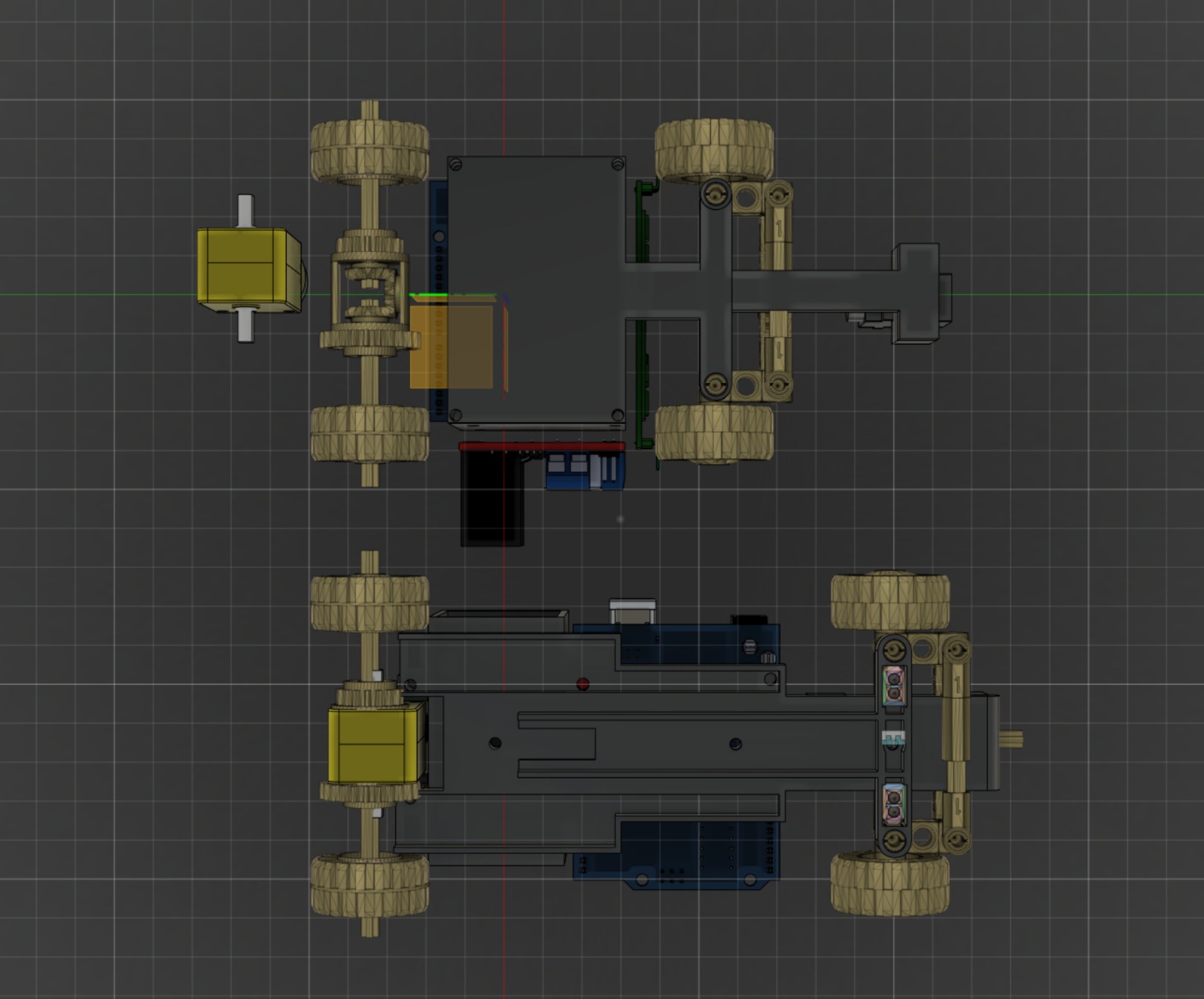
Below are a few ideas/sketches that we had while designing our car and trying to minimize the wheel base:

Given that we were trying to minimize the wheelbase in order to reduce the turning radius, we made several design choices:
- We turned the servo backwards so that it would rest in the front of the car. This meant it would reduce the wheelbase by approximately 40%
- We made sure there was enough clearance for the wheels, such that they could freely turn without hitting the 3D base plate. This allowed the wheels to turn much further and reduced the turn radius significantly.
- We kept the 6x AA battery pack vertically stacked, reducing the wheel base even further
- We moved the motor to behind the rear wheel axle, to reduce the wheelbase distance
Due to the time restrictions (we had to redesign and reprint our entire car 4 weeks from the deadline), the priority was really to get a robust car that could drive reliably and perform precise turns. So this was the motivation for the above design choices.
However, with more time we certainly could have spent much more time iterating and making our car much more sleek, which we suggest you to do:
- Try a 4x AA battery pack
- Use an ATTINY microcontroller
- Use the smaller motor controller and try to vary the voltage to change the car speed
- ...
Once you have a clear final sketch of how you want to design your car, you can start with the implementations.
For us, since we would be using some lego components in our car (the gears, the differential, the lego axles and holes, the wheels) we first need to create a 3D model that we could then import into our Fusion 360 design. We have chosen to use these Lego components since they are much more durable than 3D printed PLA/PETG and hence will make our car more robust.
In order to create the 3D lego models, we use Studio 2.0 from bricklink. Their software is incredibly easy to use, we didn't have to follow any tutorials. We recommend just trying to drag in some lego parts and move them around and build something to learn quickly.
For us, it consisted of making the front and rear axles, which we then exported into two separate models. The front axle contained the steering assembly (wheels, axles, auxiliary parts and the gears for the servo). The rear axle modelled the lego differential and the wheels. You can see this below:

Once you have made your design, you can then export it to use in Fusion 360. Unfortunately, we were unable to directly export it into Fusion 360, we must instead:
- Within Studio 2.0, File>Export As> "Collada" (.dae)
- Use an online converter to convert the .dae into a .stl file type (we used this)
- Then import it into Fusion360. You'll notice it will be incredibly big and in the wrong orientation, to get the correct dimensions you will need to:
- "Edit in place" your design, then scale down your lego model to a factor of exactly 0.04
- Rotate the lego car model as needed
You can find the Studio file we used here
Unlike Studio, Fusion 360 has a very steep learning curve and getting started will be tough (and even with experience it is a very time-consuming process). This is why we really emphasise the importance of sketching out and planning your designs on paper first, you will save days if not weeks!
The best way to get started with Fusion 360 is to follow online tutorials, since there are many great tutorials. On top of the lectures that our professor made for us, here are some useful channels:
- For beginners: https://www.youtube.com/watch?v=A5bc9c3S12g&ab_channel=LarsChristensen
- Tips to design faster and better: https://www.youtube.com/c/TylerBeckofTECHESPRESSO
There are many more resources so simply search up on Google or YouTube for these.
Regarding our designs, we tried going for a simpler body in order to save time with designing our parts and manufacturing our cars.
After 2-3 iterations we were able to finalise our design to the following:

Below you can see the comparison with the initial car design we had. You can see that all the hard work we put into sketching out and designing the car beforehand paid off, we had an almost 40% smaller wheelbase and our wheels could turn fully without any obstructions.
The main components of the 3D design is split into a dual-body design, the base plate and the battery holder:
-
The base plate connected all the wheel axles, and also held the battery box and the servo. We improved our design to include a motor axle (to hold the motor gear more steadily) and also a screwhole to add a servo axle holder (to hold it firmly against the steering assembly).
-
The battery holder is a thick case (we made it slightly too thick) where we could firmly hold the 6x AA battery pack with batteries inside. It also had screwholes across so we could secure the arduino and motor controller on top. This battery holder also had a rear segment to hold the motor in place. We later also designed a holder which we screwed onto the battery holder to hold the bluetooth module and stick the april tag on.
Thanks to this dual-body design, it was fairly simple to mount the components on (it was only a matter of screwing in the components).
With more time, it would certainly be interesting to test out a cantilever "clip-in" design, to avoid using screws, but this requires lots of trial and error, and from experience 3D printed cantilevers are not very malleable and are hard to pull out once clipped in.
You could also try make a sleek car body, to cover the entire car chassis and components making the design look much more appealing.
You can find our Fusion360 file here
Once you have all your components finalised in Fusion 360, you can File>3D Print then export your components as .stl files.
Depending on your printer set-up, you can then print out these components and then assemble your cars.
In our case, we used the Prusa printers (Original Prusa i3 MK3S & MK3S+) at our campus. We printed using 0.2MM and PETG material.
If you similarly have a prusa printer, then you need to install the Prusa software and drivers, set-up as required then import the .stl files into the prusa software.
You can then move around the components in order to minmize the support structures needed, and make sure you printed axle holes flat (printing them "vertically" will cause them to print as a slight oval due to gravity).
Then, once all your parts are printed (make sure you search online and get a proper formation on how to 3D print!) you can assemble your parts and start wiring and programming!
Since we already did an individual project with 3D printed cars, we tried to use as much as possible for our group project. It turned out quickly however that the only part we don't have to reconstruct was the steering montage. It was clear that we need a motor that has a proper gearbox so that any problems concerning basic driving can be avoided. Another problem we had with the individual project cars were the batteries. The single 9V batteries barely lasted and did not produce enough current, so we opted for 6 AA batteries instead. The components we finally used are the following:
- Battery box that has space for 6 AA batteries resulting in 9V (generate enough current for a much longer timespan than a single 9V battery)
- AA batteries
- L298N motor driver: Because this motor driver has a dual H-bridge, the cars would also be able to drive backwards. In general, this motor driver is really practical because of the very flexible voltage input of up to 12V.
- Arduino Uno: Thanks to big variety of different ports we could reduce the amount to solder to a minimum
- HC-05 bluetooth module: In order to have the cars communicate with the server and get new commands we decided to use bluetooth. The advantage of bluetooth was that the module was small and it was relatively easy to set up compared to other communication possibilities. Specifically, the module has a transmitter pin and a receiver pin besides the VCC and GND pins.
- TowerPro Micro Servo 9G SG90: A small and simple-to-use servo motor we already used for the above mentioned individual project.
- Yellow gearbox DC motor: With its built-in holes and mounting options it saved us from major gear problems.
There were two components we initially considered using:
- TCRT-5000 infrared sensors: They could have been used to locate more precisely where a car is and make appropriate path corrections. But as the system already located the cars precisely enough we did not need them in the end.
- Arduino Mini DC Motor Driver: The L298N Motor Driver was more familiar to us but this motor driver would have been possible too. They can both control up to two DC motors in both directions and with speed control.
The final wiring was the following:
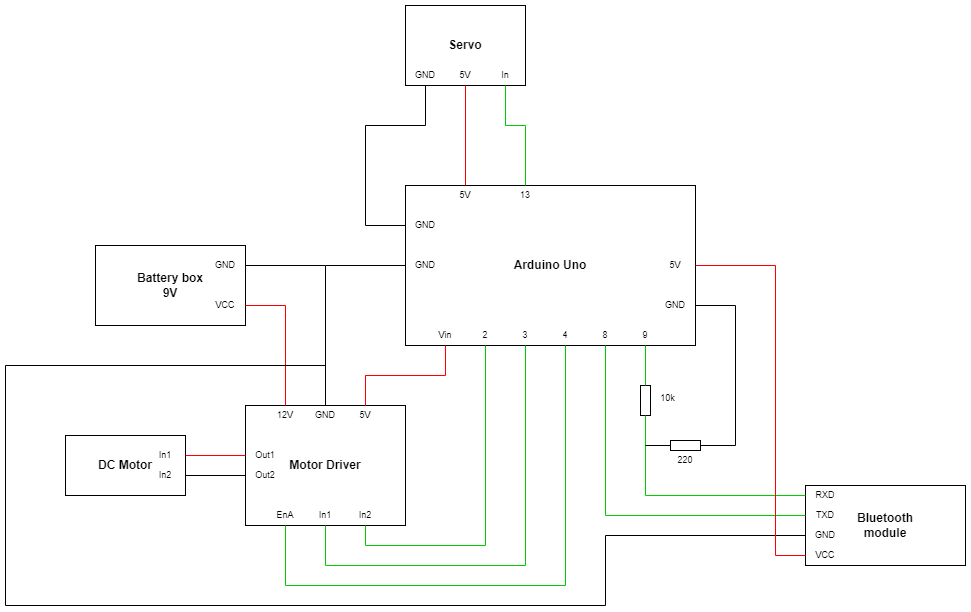
The only parts that need to be soldered are the two resistors for the bluetooth module and the wires of the battery box adapter. This is fairly straight forward by looking at your available cables and the wiring diagram above.
Make sure you have received a proper training with soldering and have watch a couple of good soldering tutorials (this one is great!)
This is what one of our finally wired cars looked like, this photo also shows the turn radius of the car. You can certainly do a better job with the cable management!

Once all the soldering and wiring up has been done, you can move on to the software part.
In this section, we assume you know the basics of Arduino Programming. With a fully-wired 3D printed car, you can now move onto programming the arduino, so it can drive the motor and steer from bluetooth commands it receives.
Our Arduino will need to be able to do 3 things:
- Control brush motor through the motor controller
- Control the Servo motor
- Communicate over Bluetooth
To control the brush motor, we need to set the IN1 and IN2 pins to opposite signals and give a speed to ENA pin. First, we have to set the pinmode of these pins to out, then we use the following code to easily control the speed of the motor:
void drive(int speed){
  if(speed > 0){
    analogWrite(enapin,speed);
    digitalWrite(motorpin1, LOW);
    digitalWrite(motorpin2, HIGH);
  } else {
    analogWrite(enapin,-1*speed);
    digitalWrite(motorpin1, HIGH);
    digitalWrite(motorpin2, LOW);
  }
}
This allows us to pass negative speeds to make the car go backwards.
Finally, for the Servo we simply use the provided Servo library:
#include <Servo.h>
We create an instance and attach it to our servo’s control pin: myservo.attach(servopin);
Now we choose a mapping of chars to actions that the car can take. For instance, when state == ‘l’ we can tell the servo to turn left. Every loop, we read a new value into state and then switch on it. Our mapping uses ‘d’ to drive forwards, ‘b’ to drive backwards, and then a wide variety of characters to represent various degrees of turning for different angles left and right.
While it is possible to do something more complicated where we buffer multiple characters or even read whole strings to specify specific angles (i.e send ”angle: 60”), in practice this is much too slow to process on an Arduino, and for our feedback loop we want minimum response time. Furthermore, we found that packets are frequently dropped on our HC-05, so resending single chars is much easier than sending whole strings.
We also need to make sure that the cars’ turning is centered so that we don’t break the turning mechanism. Since our Servos accept an input range from 0-180, straight will be at 90 degrees for us. We defined the following method to avoid confusion:
void turn(int angle){
    myservo.write(90+angle);
}
So giving a negative angle will turn us right and a positive angle will turn us left.
Our exact turn mapping looks as follows:
//left
  if(state == 'q') turn(90);
  if(state == 'a') turn(80);
  if(state == 'y') turn(70);
  if(state == 'w') turn(60);
  if(state == 's') turn(50);
  if(state == 'x') turn(45);
//right
  if(state == 'p') turn(-90);
  if(state == 'k') turn(-80);
  if(state == '-') turn(-70);
  if(state == 'o') turn(-60);
  if(state == 'l') turn(-50);
  if(state == '.') turn(-45);
The turning angles were chosen after a lot of experimentation.
To achieve the first task, we will use the SoftwareSerial library: #include <SoftwareSerial.h>, which should come by default with the Arduino IDE. This will allow us to treat the HC-05 as a Serial port, just like writing to and reading from the Serial Monitor on the IDE.
We can instantiate a new instance of SoftwareSerial by giving it two pins to read from (RX and TX of the HC-05, respectively): SoftwareSerial MyBlue(8,9);. To read, we simply use the following code:
if(MyBlue.available()){
    state = MyBlue.read();
}
Here, we assume basic knowledge of python and sockets. In this section, we will make a basic “remote control” for our cars from our laptop. Make sure your python installation comes with bluetooth (we use miniconda). Before we write any code, we need to know the MAC Address of our HC-05. Power up the car you want to connect. On Windows, you can find the MAC address under Control Panel\Hardware and Sound\Printers and Devices.
The following code connects your computer to the HC-05:
import socket
addr = ‘FF:FF:FF:FF:FF:FF’#your address here
s = socket.socket(socket.AF_BLUETOOTH, socket.SOCK_STREAM, socket.BTPROTO_RFCOMM)
port = 1
s.connect((addr,port))
Many errors can occur here. The main one is Encountered a Dead Network which occurs when your device Bluetooth is turned off.
Next, all we need to do is loop forever and ask for commands:
while True:
        command = input()
        s.send(command.encode())
If you run this program, you should be able to drive your car by inputting characters in your command line.
We can also define some utility functions to automatically encode the correct characters based on what we want to do, for example:
def turn(angle):
    angles = [90,80,70,60,50,45,0]

    left = ['q','a','y','w','s','x','g']
    right = ['p','k','-','o','l','.','g']

    if angle > 0:
        return left[angles.index(angle)]
    return right[angles.index(-angle)]
In this section, we will use an open source fiducial marking system known as AprilTags to locate our cars. AprilTags are essentially simple QR codes which are really easy for a computer to identify and locate, but carry much less information. By placing a tag on each car and ceiling-mounting a camera, we can “simulate” a GPS. AprilTags are especially nice since there is open source code for detecting them.
Unfortunately, all versions we found are built for old versions of Python and we will need to do some hacky things to use this library. First, make sure OpenCV is installed using pip. Now, we need to build Python wheels, which for some reason requires Visual Studio 2017 (NOT any newer version) with the C++ Development kit (downloadable here). Then, we clone the AprilTags detection repo: git clone --recursive https://github.com/pupil-labs/apriltags.git
Now, if you are running a python version >= 3.8, you will receive an error about DLL files if you try and install this using pip. This is because the way Python searches for libraries changed in 3.8. To combat this, we need to go into their apriltags.src/pupil_apriltags/bindings.py file and add the kwarg winmode = 0 to the function called in line 285. Don’t ask how many hours it took to figure this out. Now, you can “simply” run pip install -e .[dev] to complete the installation.
It’s smooth sailing from here. Print a couple of tags (or, to save paper, pull up a picture of a tag on your phone), then using opencv you can pull up a video stream from your webcam:
import cv2
cap = cv2.VideoCapture(0)
while True:
        ret, frame_in = cap.read()
        if cv2.waitKey(1) & 0xFF == ord(‘q’):
                break
        cv2.imshow(‘camera’, frame_in)
To detect AprilTags, we just need to instantiate a detector and call it on a grey version of frame_in:
from pupil_apriltags import Detector
import cv2
at_detector = Detector(families='tag36h11',
                       nthreads=1,
                       quad_decimate=1.0,
                       quad_sigma=0.0,
                       refine_edges=1,
                       decode_sharpening=0.25,
                       debug=0)
cap = cv2.VideoCapture(0)
while True:
        ret, frame_in = cap.read()
        grey = cv2.cvtColor(frame_in, cv2.COLOR_BGR2GRAY)
        tags = at_detector.detect(grey)
        for tag in tags:
            cv2.putText(frame_in, str(tag.tag_id), (int(tag.corners[1][0]),int(tag.corners[1][1])), cv2.FONT_HERSHEY_SIMPLEX, 1, (255,0,0), 3,cv2.LINE_AA)
            cv2.rectangle(frame_in, (int(tag.corners[0][0]),int(tag.corners[0][1])), (int(tag.corners[2][0]),int(tag.corners[2][1])), (255,0,0), 2)
        cv2.waitKey(1) & 0xFF == ord(‘q’):
                break
        cv2.imshow(‘camera’, frame_in)
This simple program draws squares around each AprilTag it sees, along with the tag’s ID.
The AprilTags are really cool because by giving the detector the size of the tag and the distortion coefficients of the camera, it can automatically tell you where in space the tag is in meters. Unfortunately, even after a lot of experimenting with chessboards, we found this wildly inaccurate, and as far as we’re concerned, cars only exist in a 2d plane. We could just take the pixel coordinates of the tags, but this wouldn’t work well due to the aforementioned camera distortion; camera lenses are curved, and so straight lines on the camera are curved in real life, especially towards the camera’s edges. We opted instead to define our “world” as a rectangle whose corners are defined by AprilTags. We can compare the pixel coordinates of the corners and define a coordinate system based on how far between AprilTags we are. This doesn’t solve the problem of camera distortion, but it lessens the effect significantly. This code can be found in the file Translator.py for those interested.
Finally, we get to the good part: self-driving cars! Again, here I will only give a basic algorithmic overview, but using the code seen in previous parts, this shouldn’t be too difficult to implement.
In order to simulate traffic or pick up passengers, we should be able to tell the cars to go to arbitrary points in our map. Then, if we have to follow roads according to those so-called “cops”, we can just use Dijkstra’s Algorithm on our road network to find a list of points that we have to pass through, feeding the first point in the list to our feedback loop until we reach it. In this part we will go over how to reach just one point.
Our car is facing in a certain direction. If we drive forwards, we might go in this direction, but probably not. The wheels might be slightly misaligned, or the road not entirely flat. So, even if we are facing our goal, we must constantly course-correct to reach our target, and that’s assuming we started off facing our target. In this implementation, we constantly drive forward with no regard for the car’s wellbeing. There are better methods where the car will drive backwards in order to arrive at the goal faster, but this becomes extremely complicated extremely quickly, and when the end goal includes multiple cars driving in the same streets and not crashing, having half of them randomly choose to drive backwards will not help.
The algorithm proceeds in an infinite loop as follows: We check the direction of the car (we can get this from the April Tags, as the detector provides us with the corners of the tags). Then, we can check the direction we should be going, i.e the vector from our car’s center to the goal. Now we find the angle between the two vectors. If the angle is zero, we should tell the car to go straight. If the angle is between 0 and 180 degrees, we should go right to end up facing the goal, and if it’s between 0 and -180 we need to turn left. After we tell the car which direction to turn, we just check the angles again, and apply new turns as needed, until we reach the goal.
Sounds easy, right?
Unfortunately, we have some problems. First of all, we will probably never see the angle equaling zero, even if we cast our angles to ints, since our april tag might be slightly rotated or our detection might be slightly imperfect. So, in practice we will never go straight and always snake to the finish line, which is undesirable and will land you a DUI. So, we add a little tolerance, and go straight if we’re facing within 10 degrees of the target. Then, the other problem: How much should we turn when we’re not facing the target? If we’re facing 11 degrees away from the target, and we make a turn which is too sharp, we will end up facing -11 degrees before the camera can detect that we were ever supposed to go straight, and we’re back to snaking. We can no longer increase the tolerance for going straight either, since we will end up missing the target if we increase it any further. So, we have to take less sharp turns. This leads to a different problem: we might not be able to make a sharp enough turn to ever reach the target! If the target is directly behind us, say, then we might just end up circling forever, unable to reach it. This is why we have so many turning commands: we need to make super sharp turns when we are facing far away from the target, and as we close the angle between us and the goal, we slowly taper off the amount we turn. This turns out to work quite well.
Our basic traffic controller is used to simulate regular traffic interacting at five intersections. Each car is assigned a destination at random and begins driving there. When two cars come to an intersection, they are added to a waiting queue to be allowed through the intersection. Although we could not simulate it with our physical cars, our virtual simulation also allowed us to make these cars “autonomous” cars who could tell their intended paths to one another, allowing multiple cars through the same intersection when their paths don’t cross.
We will give a very quick rundown of the structure of our codebase. Our simulation code is all written in Python, so we highly recommend you watch tutorials on python and python object-oriented programming. Also make sure that you are familiar with object-oriented concepts and advanced elements such as inheritance.
Note: Due to problems with python, it was too tedious for us to implement packages (we initially had them but had to remove the packages since we were unable to properly import the classes from the files).
Below you can find the UML diagram that we designed and used as a reference to coding our classes.

We recommend that you try reading through our codebase to understand more how each class interacts with each other.