Home
It is advised to follow tutorials in the order shown in
Pageson the top-right if you are just starting out.
Please memorize (or keep a reference of) this image as these terms are frequently used throughout tutorials.
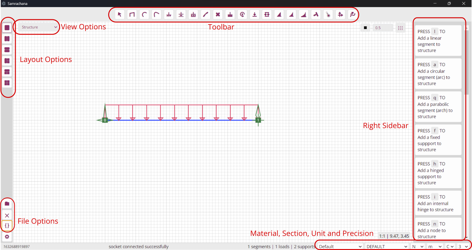
Image: A screenshot of samrachana-web
The application interface can be divided into five regions:
- Toolbar on the top
- Left Sidebar with Layout options, File options and Settings
- Right Sidebar with hints and forms as required
- Statusbar at bottom with messages and options for material, section, units and precision
- Main region where structure is plotted, and relevant data is displayed
While modeling, analysing or calculating diagrams, every input from user is taken from the right sidebar. So, except when setting coordinates by clicking on the graph, the form displayed on the right sidebar should be submitted.
A view is where graphs and tables are displayed. There are four views available, switchable as required via View Options. They are:
- Structure - Graph of structural elements: segments, loads and supports
- Members - List of elements with all properties. Segment properties obtained from section and material chosen can be overridden here.
- Analysis Result - Table showing reactions, actions and responses after analysing (solving) the structure
- Vector Diagrams - Diagrams of interest plotted over segments, like AFD, SFD, BMD and resultant displacement.
Samrachana offers six different layout options. Each layout allows one or more views to be displayed on the main region. They are listed in order as they appear in layout options.
- One - Default layout suitable for modeling the structure
- Two Horizontal - Suitable for editing the modeled structure
- Two Vertical - Suitable to see analysis result
- Three Horizontal - Suitable to see diagrams, structue and analysis result focusing on diagrams
- Three Vertical - Similar to above, but suitable when focusing on structure
- Four - Useful when required to see all four views at once
When appropriate the application switches to different layouts. But, each view in every layout can be changed via View Options.
Every tool in the toolbar can be quickly toggled by keyboard shortcuts. They are listed below:
| Key | Tool | Description |
|---|---|---|
Esc |
None | Displays shortcut hints on right side bar |
x |
Select | Allows user to select members to edit or delete them |
l |
Line | Add a line segment |
a |
Arc | Add an arc segment (circular arc by three points) |
q |
Quad | Add a parabolic segment (arch) |
f |
Fixed | Add a fixed support |
h |
Hinge | Add a hinged support |
r |
Roller | Add a roller support |
i |
Internal Hinge | Add an internal hinge (snap to a segment via form on right side bar) |
n |
Node | Add a node (a redundant support for including important points during analysis) |
c |
Custom | Add a custom support like for resisting Horizontal force and moment only |
m |
Moment | Add a moment load to a segment |
p |
Point | Add a point load to a segment |
u |
UDL | Add a uniformly distributed load to a segment |
v |
UVL | Add a uniformly varying load to a segment |
w |
Parabolic | Add a quadratic distributed |
z |
Cubic | Add a cubic distributed |
s |
Misfit | Add a misfit (changed to appropriate loads) to a segment (Only peak and parent segment on the form on right side bar are used. Other parameters are redundant) |
t |
Temperature | Add a temperature variation (changed to appropriate loads) to a segment (Only peak and parent segment on the form on right side bar are used. Other parameters are redundant) |
, |
Analyse | Solve the structure (Just toggling the tool is not enough. Please press Analyse Structure button on the right side bar) |
. |
Diagrams | Calculate Diagrams (Just toggling the tool is not enough. Please press Calculate Diagrams button on the right side bar) |
- Positive X distances and Forces : Left to Right
- Positive Y distances and Forces : Down to Up
- Positive Angles and Moments : Anticlockwise
- Segment axial axis : Initial Coordinates to Final Coordinates
- Segment shear axis : Axial axis rotated by 90 degrees anticlockwise
- Segment angular axis : Anticlockwise positive