

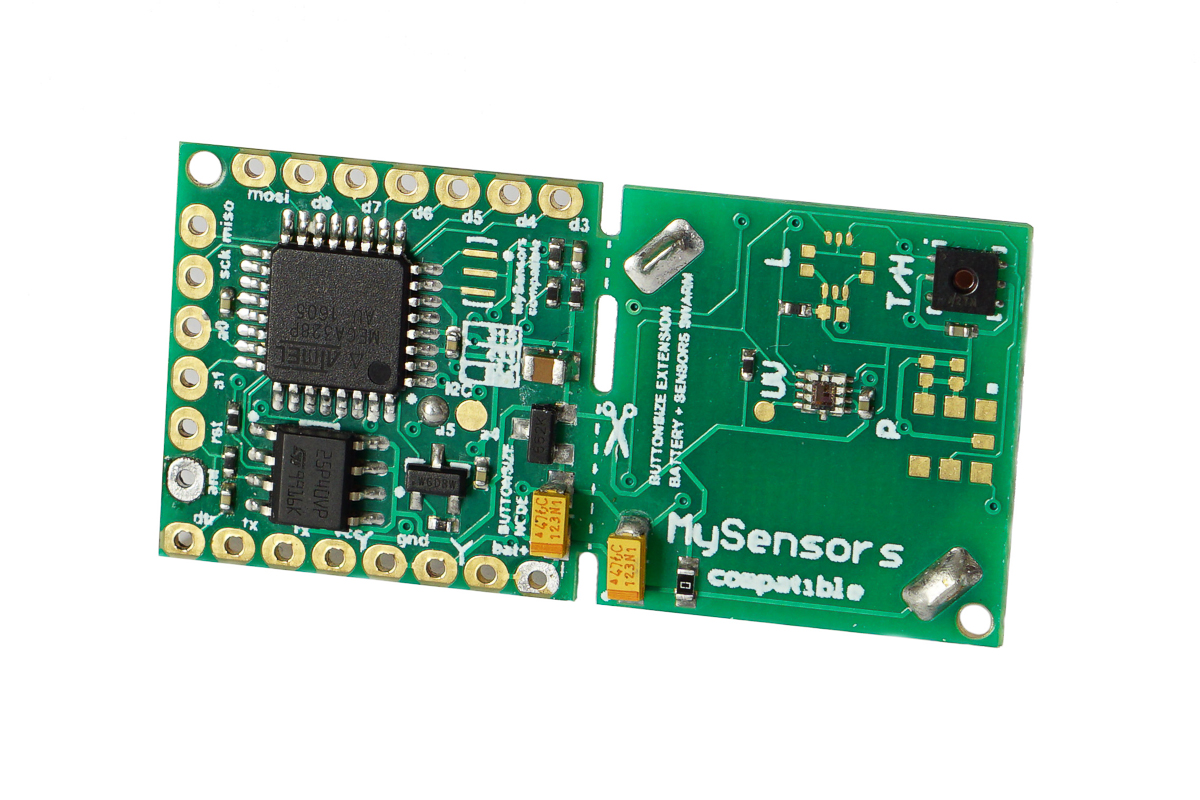
The Button Size Node is a low cost wireless Arduino IDE compatible (the Atmel ATMega328P 8MHz) microcontroller with RFM 69 HW(CW) radio on board and few other nice additions.
Best sutable for Home Automation, IOT. Could be used as core board for radio controlling any DIY project. You may think of it as Arduino Pro Mini plus all the items in the picture below::

- Dimensions 42.2mm x 20.9mm
- Sleep current consumption 10 - 12 uA
- Temperature and humidity sensor Si7021
- High Accuracy Temperature Sensor ±0.4 °C (max), –10 to 85 °C
- Precision Relative Humidity Sensor ± 3% RH (max), 0–80% RH
- Light sensor BH1750, spectral responsibility is approximately human eye response.
- Authentication security - Atmel ATSHA204A Crypto Authentication Chip
- External JDEC EPROM
- Dualoptiboot bootloader. Implements over the air (OTA) firmware update ability
- RFM69-HW (high power version) or CW (low power consumption version) 433 MHz Radio transceiver
- Battery voltage sensor (via divider)
- Supply voltage up to 6.5 Volts
- The Digital and Analog pins are 3.3 volts
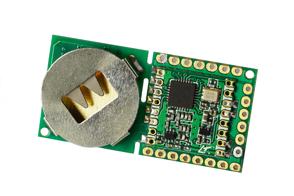
- Battery connector CR2032 240mAh
- FTDI header for programming
- You can cut with scissors, sensors and battery holder part, if you need just controller and radio
Pin out:
| Arduino Pins | Description |
|---|---|
| A0, A1 | Available ARDUINO analog GPIO / DIGITAL GPIO |
| A6 | Connected to Battery voltage sensor (via divider) |
| A4 | Connected to si1132 and bh1750 SDA |
| A5 | Connected to si1132 and bh1750 SCL |
| A3 | Connected to ATSHA204A |
| D3, D4, D5, D6,D7, D9 | Available ARDUINO digital GPIO |
| D8 | Connected to CS FLASH chip (OTA) M25P40 |
| MISO, MOSI, SCK, RST | Connected to ISP header |
| ANT | RFM69 antenna |
| Vcc and Bat+ | Unregulated power up to 6.5 Volts |
| Gnd | Ground |
| Scissors line | you cat cut with scissors, sensors and battery holder part, if you need just controller and radio |
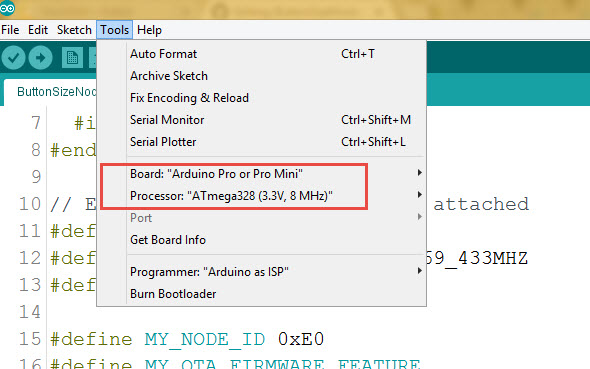
Arduino IDE Settings
programming FTDI adapter connection

Both 3.3V and 5V power options can be used.
ButtonSizeNode.ino is the Arduino example sketch using MySensors API.
-
Controller Setup.
Burn the ButtonSizeNode.ino sketch into the board and it will became one of the MySensors home automation network Sensor's Node reporting Temp, Humidity and Vsial light in Luxes to a smarthome controller. To create the home automation network you need smarthome controller and at least two Nodes one as a Sensor, a Relay or an Actuator Node and the other one as the “Gateway Serial” connected to a smarthome controller. I personally love Domoticz as a smarthome controller. Please check this HowTo to install Domoticz. -
No Controller setup. However, for no-controller setup, as example, you can use 3 nodes - first node as the “Gateway Serial”, second node as a Relay and last one as a Switch for that Relay. No controller needed then, keep the Switch and the Relay on the same address and the switch will operate the relay.
Things worth mentioning about the MySensors Arduino sketch:
| Code | Description |
|---|---|
| Light meter BH1750 Library by Christopher Laws | MySensorsArduinoExamples BH1750 |
| Temperature and humidity sensor Si7021 SparkFun Library | SparkFun_Si7021_Breakout_Library |
| #define MY_RADIO_RFM69 #define MY_RFM69_FREQUENCY RF69_433MHZ #define MY_IS_RFM69HW |
Define which radio we use – here is RFM 69 with frequency 433 MHZ and it is HW type – one of the most powerful RFM 69 radios. If your radio is RFM69CW - comment out line with // #define MY_IS_RFM69HW |
| #define MY_NODE_ID 0xE0 | Define Node address (0xE0 here). I prefer to use static addresses and in Hexadecimal since it is easier to identify the node address in Domoticz devices list after it will be discovered by controller ( Domoticz). However, you can use AUTO instead of the hardcoded number (like 0xE0) though. Domoticz will automatically assign node ID then. |
| #define MY_OTA_FIRMWARE_FEATURE #define MY_OTA_FLASH_JDECID 0x2020 |
Define OTA feature. OTA stands for “Over The Air firmware updates”. If your node does not utilize Sleep mode you can send new “firmware” (compiled sketch binary) by air. Here is the link on how to do it. Skip to the step "How to upload a new sketch just with OTA" as all initial steps have been completed in the ButtonSizeNode. For OTA we use JDEC Flash chip where the node stores new firmware and once it has been received and checksum (CRC) is correct it reboots and flashes your new code into the node controller. 0x2020 "Erase type" defined here for JDEC Flash chip . |
| #define MY_SIGNING_ATSHA204 #define MY_SIGNING_REQUEST_SIGNATURES |
Define if you like to use Crypto Authentication to secure your nodes from intruders or interference. After that, you have to “personalize” all the nodes, which have those, defines enabled. How to “personalize” nodes with encryption key. You need both defines in the nodes you need to protect. The Gateway Serial could be with only one of those defines enabled - #define MY_SIGNING_ATSHA204 |
Connect the Node to FTDI USB adaptor, Select Pro Mini 8MHz board in Arduino IDE and upload the ButtonSizeNode.ino sketch.
Done
The board is created by Koresh
For schematics lovers:
