GAGGIA CLASSIC
-
Needed to upload the code ".ino" to the arduino ROM
Libraries to add:
Library manager: - Easy Nextion Library - MAX6675 by Adafruit - TimerInterrupt_Generic External libraries: - PSM > https://github.com/banoz/PSM.Library - HX711 > https://github.com/banoz/HX711 -
Only necessary if planning on editing the ".HMI" file to ammend the LCD functionality
-
USB driver so your system recognizes the Arduino clone board, let's say i have found this the hard way as apparetly the majority of cloned arduinos use a cheaper USB controller comparing to "genuino"
Schematics:
Diagrams:
!! WARNING !!
First and foremost please do not underestimate the danger of electricity or overestimate your ability to work around it. Only start working on your machine while it's completely disconnected from the mains power socket, also by agreeing to follow the below guide I cannot be deemed responsible for any of the damage you induce to your house appliances, yourself, your cat, friend or gold fish and it will be entirely your fault!
First we need to understand what goes where. The schematics aren't really rocket science but for someone who's never disassembled or has no experience working with electrical circuits it might get confusing really fast so I will try to describe it as simple as possible yet limited by my vocabulary. First let's check that the setup works as expected while outside the machine so you don't have it all installed and realise just afterwards it's not reading any temperature because of a faulty component or the relay doesn't switch between the ON/OFF modes.
Note 1 - no permanent connections are needed during testing so no soldering needed for now.
Note 2 - the 5v/GND Arduino board pins will be shared between all the connected devices.
-
The first step will be connecting the MAX6675 module to the arduino board using the pins defined in the code. You can find them defined at the top of the .ino file.
MAX6675 Arduino VCC 5v GND GND SCK D6 SO D4 CS D5 -
Connect the relay. For now only connect the circuit controlling ports to check whether the relay LED indicates the power states.
Relay Arduino 4 GND 3 D8 Relay ports [1] and [2] are the high voltage circuit breaker
-
Plug the arduino board in using the mini USB cable that came with it and upload the code to the arduino board.
Note: uploading won't work with the LCD connected
-
Nextion LCD wiring
Nextion Arduino TX RX RX TX VCC 5v GND GND -
Uploading the LCD ROM code
Method 1
Just copy the *.tft file on a FAT32 formatted microSD card and upload onthe LCD panel using the onboard card readerMethod2
Open the .HMI file using Nextion Editor and using the File menu upload it on a microSD cardNote: card needs to be FAT32 formatted
-
After the upload is finished get the card out and power cycle the LCD.
-
You should see temp readings on your screen if everything went according to plan.
Don't forget to test the thermocouple/relay combo operation, apply some heat to the thermocouple end and see whether the relay led operates in HIGH/LOW modes
Due to the way the Arduino design works as well as the nature of how the on-board ADC functions in order to avoid a loop in regards to the BREW MODE it's required to connect the pins A0 -> GND, this is only needed if the ACS712 sensor board is not connected to the Arduino.
At this point if all the above works as expected you're ready to install it all inside the machine. For this we'll need to prepare some splitters that we'll use to connect to the Gaggia internals without introducing any permanent modifications so in the event of a desire to revert to stock it's a few disconnects away!
POWER DELIVERY RECOMMENDATION
Powering using the [ 12v ] power supply module + [ 5v ] stepdown convertor is the recommended way, follow the bellow scheme:
| PS | Arduino |
|---|---|
| 5v | 5v |
| GND | GND |
Powering all the arduino connected boards through the USB port is not recommended due to the low power capacity of the on-board voltage regulator, this will kill your arduino eventually you've been warned!
STEAM DETECTION
Gaggia Classic:
- Disconnect all the steam switch high voltage wires
- Bridge the wires connected to the steam switch poles 1 and 2.
- Bridge the steam thermostat wires.
- Connect steam switch poles 3 and 4 to the arduino nano like in the table bellow using some AWG26 wires.
- Make sure you secure all the left disconnected wires so they don't make any accidental contact.

| GC SWITCH | Arduino |
|---|---|
| 3 | D7 |
| 4 | GND |
BREW DETECTION
Will look slightly different for people using a GC vs those with a GCP
GAGGIA CLASSIC:
| OPTOCOUPLER | Arduino |
|---|---|
| VCC | 5v |
| GND | GND |
| OUT | A0 |
The high voltage circuit control ports will splice into existing brew switch wires.
DIMMER
| Dimmer | Arduino |
|---|---|
| VCC | 5v |
| GND | GND |
| Z-C | D2 |
| PSM | D9 |
Dimmer high voltage circuit control ports will act as a passthrough for the pump LIVE and NEUTRAL wires
PRESSURE HANDLING
| Transducer | Arduino |
|---|---|
| RED | 5v |
| BLACK | GND |
| YELLOW | A1 |
ATTENTION !!!
As always with such projects common sense should be applied at all times, it's expected people doing such sort of modifications will have some basic understanding.
AGAIN!!! Triple check your machine is disconnected from any power sources, even better just pull the power cable out of it if you haven't done so yet!
- Take off the top cover by unscrewing the 2 top screws. You should be able to see something similar to the below image minus the SSR relay:
- Prepare 2 splitters like in the below image using the AWG15 cable, be sure one splitter to be black(negative) and one red(positive)
- Be sure to mark your top left power connector so you don't mix them up ( even though it's not that hard to understand which one is which)
- Disconnect all 3 of them as you'll use the midlle and bottom ones for power sharing.
- The hardest part will be now in my opinion as you'll have to unscrew the bottom boiler stock thermostat and screw back in the new thermocoule. Be sure to apply some thermal paste on the thermocouple threads. (Just a teeny tiny bit.)
- Prepare 2 cables you'll use to connect the cables disconnected from the thermostat to the port 1 and 2 of the SSR relay. Use the red cable for that. They shouldn't be too long, about 10cm will suffice, one end should be crimpled with a male spade connector and the loose end screwed to the relay and attach the relay to the machine case itself, I have no clue what screw size I used as i have just matched one by trial and error lol, but be sure to apply some thermal paste to the SSR backplate that will make contact with the metal case of the machine.
So you end up having them connected like this:
- Prepare 2 more 10cm cables( also colour coded accordingly) which should be crimpled with M/F spade connectors at each end, the female end will go in Gaggia's front panel and the male end will go to the female end of the previously prepared (2) splitters, as in the below image:
-
Connect the front panel cables to any of the free male ends of the splitters as well, black one for the negative cable and red for the positive one (on my machine the positive is having 2 cables crimped together).
-
To power the Arduino system I have used an old 5v mobile charger which I'm sure all of us have laying around. Just solder 2 cables to the 2 ends of the charger and for the other ends use 2 F spade connectors, after which plug them to the remaining 2 splitter (2) ends.
- Now you're ready to connect everything to the arduino like you did it when testing everything, one piece of advice would be to solder all the Arduino connected cables as during the machine operation there is quite a bit of vibration and that can introduce all sorts of noise/frequent disconnects to certain pins which will lead to unexplained behaviours.
- BREW DETECTION
Gaggia Classic(pre 2018) ONLY

- Prepare two "Y" splitters BLACK and RED with the ends crimped as follows:
- RED SPLITTER: 1 x MALE, 1 x FEMALE, 1 x BARE.
- BLACK SPLITTER: 2 x FEMALE, 1 x BARE.
- Wire connected to STEAM button pole 4 connects to BREW button pole 5, original disconnected BREW pole 5 wire should be left disconnected but properly secured.
- Connect the RED "Y" splitter to BREW switch pole 6 and plug the original connected wire to the MALE spade end, the BARE splitter end going to the optocoupler L terminal.
- Tap into the PSU splitter used for the N connection using the BLACK splitter and connect the bare end to the optocoupler N
- Installing the RobotDYN dimmer module.


The image above is provided as a reference to understand how the connection through the dimmer is made, please check whether your dimmer high voltage ports placement differs from the above image before connecting the dimmer, it's very important to feed the IN wires properly.
- Installing the pressure transducer. The pressure sensor will be tapping into the hose connecting the pump outlet and the boiler inlet, the way people connect it is up to individuals.
It's advisable after making the connections and just before connecting the transducer itself turn on the machine and while cold engage the pump to fill the transducer hose with water as well, leaving a lot of air in the system might play funny with the readings.


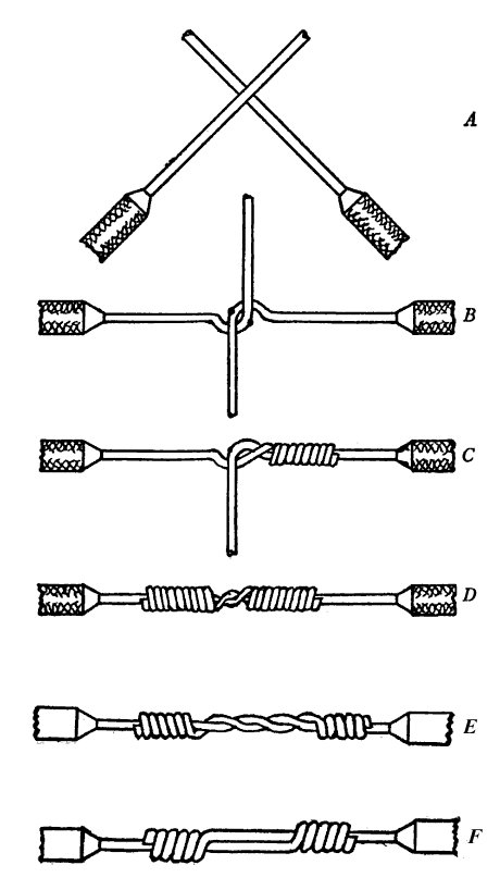
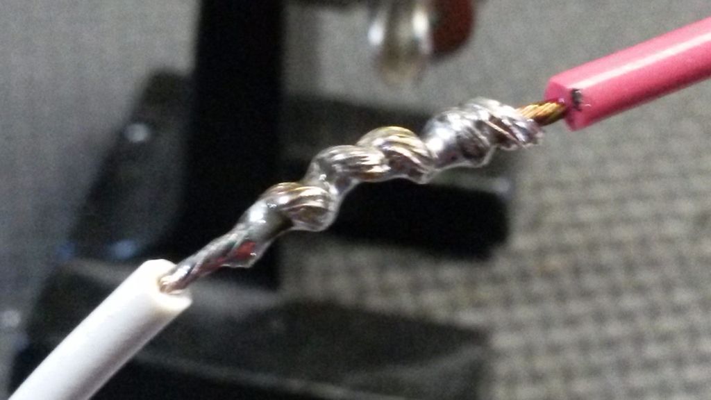
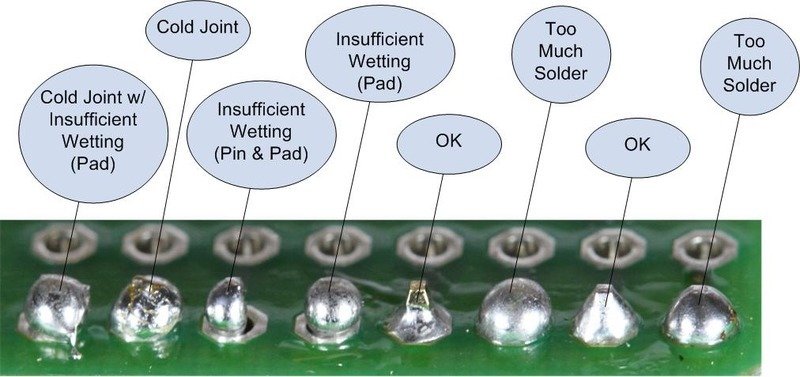
- Take your time soldering perfectly
- Use the "Western Union" splice to link wires (GND and 5v)
- Tin your wires to make them easier to solder.
- GitHub: https://github.com/Zer0-bit/gaggiuino
- Discord: https://discord.com/channels/890339612441063494/890339612441063497
- Soldering 1: https://youtu.be/Fb7ONG08BUk
- Soldering 2: https://youtu.be/Fp37DPZVdRI
- Crimping : https://youtu.be/nvPESov0HbY
- Nextion : https://nextion.tech/faq-items/using-nextion-microsd/