GAGGIA CLASSIC PRO [ECO & NON ECO]
-
Needed to upload the code ".ino" to the arduino ROM
Libraries to add:
Library manager: - Easy Nextion Library - MAX6675 by Adafruit - TimerInterrupt_Generic External libraries: - PSM > https://github.com/banoz/PSM.Library - HX711 > https://github.com/banoz/HX711 -
Only necessary if planning on editing the ".HMI" file to ammend the LCD functionality
-
USB driver so your system recognizes the Arduino clone board, let's say i have found this the hard way as apparetly the majority of cloned arduinos use a cheaper USB controller comparing to "genuino"
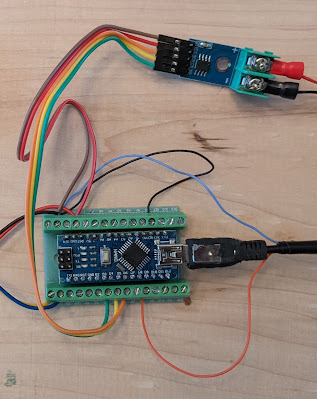
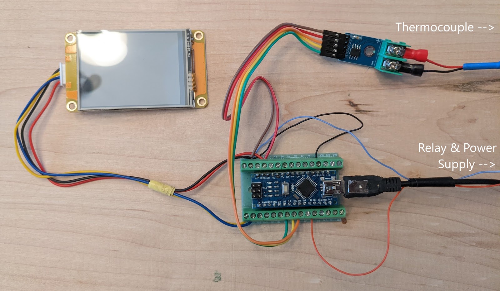
We are not installing inside the machine yet and we are doing minimal soldering at this point. We just want to test as much as we can to make sure we've not got any duds from a base functionality point of view.
We need to understand what goes where. The schematics in (3.0.1 Schematics & Diagrams) aren't really rocket science but for someone who's never disassembled or has no experience working with electrical circuits it might get confusing really fast.
Note 1 - No permanent connections are needed during testing so no soldering needed for now. Note 2 - The 5v/GND Arduino board pins will be shared between all the connected devices.
Place Arduino into the expansion board the correct way round. Power it through USB adapter for now during the testing phase.
Image of Arduino with pins soldered:
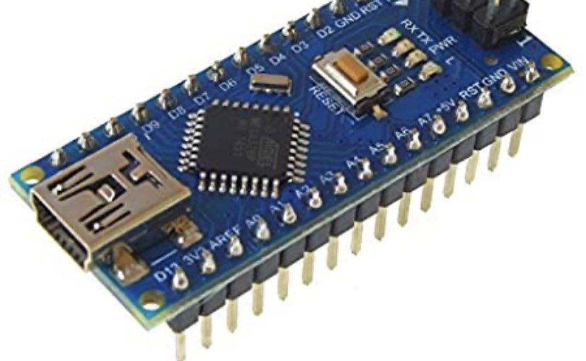
Image of expansion with pins (solder from the bottom):
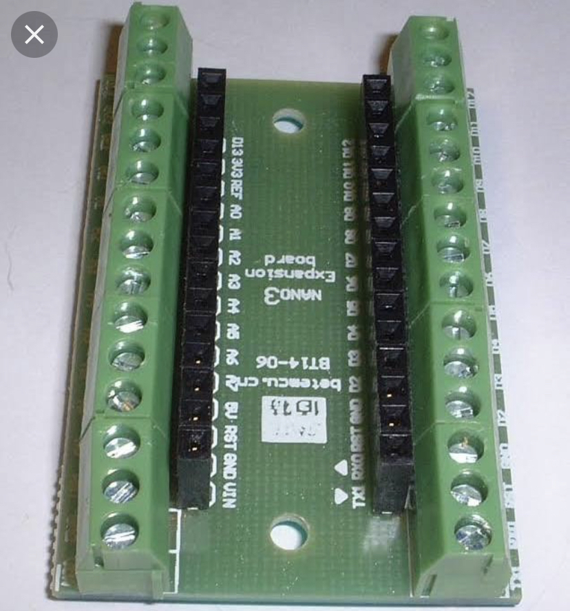
Make sure the terminals are correct way round and place the Arduino into the expansion board.
If you have to solder your pins then take the time now to get your soldering perfect. It'll save time in the long run. REFER TO APPENDIX 3.0.3 Recommendations FOR SOLDERING GUIDES!

Attention! You are not soldering the Arduino to the expansion board itself. You are only soldering the pins to the Arduino and pins to the expansion board. The Arduino then just sits/connects into the expansion board pins.
For the below section you are using 26AWG cable to connect to the Arduino board.
Refer to the appendix 3.2 for component wiring.
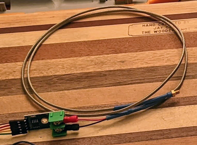
You should have bought and received a MAX6675 board which comes with a test thermocouple. We're swapping this for the "C-M4 screw K-Type thermocouple sensor" as this is what will be replacing the original that's in the machine.
For the below section you are using 26AWG cable to connect to the Arduino board.
Refer to the appendix 3.2 for component wiring.
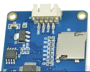
The correct screen size is 2.4". If yours does not have markings for wiring then please see below image
For the below section you are using 26AWG cable to connect to the Arduino board.
Refer to the appendix 3.2 for component wiring.
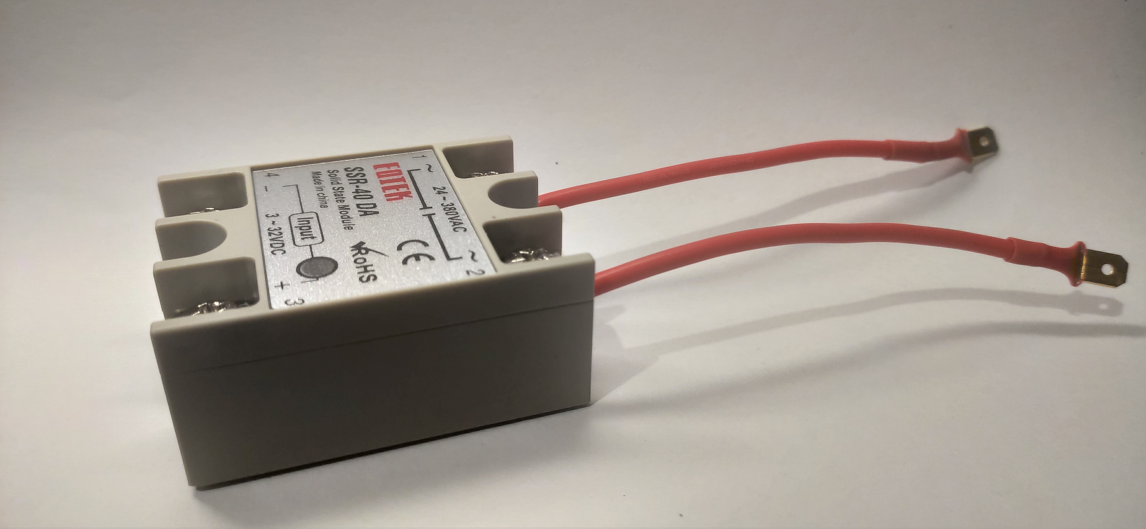
This relay is what manages the temp by cutting the voltage when the thermocouple is at a set temp.
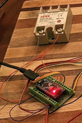
Plug the Arduino board into PC/Mac using the mini-USB cable that came with it and upload the code to the Arduino board. Note: Uploading won't work with the LCD connected
- Download/Install Arduino IDE
- Download/Install CH340 USB Driver
- Download the latest version of Gaggiuino from the GitHub main repository. Copy the unzipped files to an easily accessible location
- Add Libraries:
- Click Sketch\Include Libraries\Manage Libraries
- Type in the Library name and install most recent version
- Install 2 Libraries:
- Easy Nextion Library
- MAX6675 by Ada-fruit
- Add External Libraries:
- Download Library Zip Files:
- PSM Files must be unzipped to the Arduino Library folder (default path is located in your local documents folder. You should see the added libraries from step 4 here as well.)
- Open Gaggiuino.ino (located in Gaggiuino folder from step 3). If prompted to create a sketch folder, press OK
AT THIS POINT AFTER INSTALLING LIBRARIES RESTART THE IDE SOFTWARE
- Unplug the LCD from our Arduino Board mock setup
- Plug the Arduino in via USB cable (must be a data transfer cable, not just a power cable)
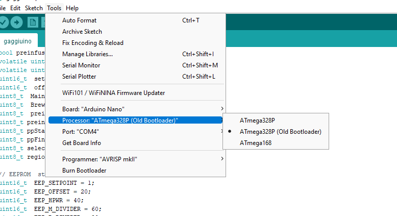
- Set Board, Processor, Port: Navigate to “Tools” in the top menu:
- Board: “Arduino Nano”
- Processor: “ATmega328P”
-
- Use the “Old Bootloader” version, but results may vary depending on your hardware.
-
- When plugged in and the “port” section should be active and something should be selected. If not manually select the port that contains the Arduino. Mine was on “Com4”. Try unplugging then plugging in again if it doesn't work.
- Press Upload (Make sure LCD is UNPLUGGED before uploading otherwise upload will fail)
- If upload is Successful, unplug Arduino Board from computer
Uploading the LCD ROM code Method 1 - Download and unzip the *.tft file on a FAT32(MS-DOS (FAT32)) formatted microSD card and upload on the LCD panel using the onboard card reader.
Method 2 - Open the .HMI file using Nextion Editor and using the File menu upload it on a microSD card
- Plug LCD back into Arduino Board Setup
- Locate “nextion-discovery-lcd.tft” or “nextion-basic-lcd.tft” (depends on what you purchased)
- Copy the file to a FAT32 formatted MicroSD card
- If on Mac for some reason it adds a second file beginning with a "." use terminal to change directory to the microSD and use "rm ._nextion-YOUR-VERSION-lcd.tft" to remove that file.
- Place MicroSD card inside the Nextion display
- Power on the Arduino Board Setup and installation should occur automatically
- Once “successed” reboot the Arduino
You should now see the Gaggiuino project on the LCD. If your connections are all right (and well secured), you should see a temperature reading from the thermocouple (temp reading will contain the default offset of 7 which means the initial temp will be - room temp -7)
Try applying heat with your hand and you should see the temperature respond (if not, I recommend confirming all connections are correct and adequately tightened. Mine did not respond at first and turned out one of the connections to the Arduino board was not tight enough)
If everything looks good, move on to Installing into the Gaggia Classic Pro
If all the above works as expected you're ready to install it inside the machine.
!! WARNING !!
Do not underestimate the danger of electricity or overestimate your ability to work around it.
Only start working on your machine while it's completely disconnected from the mains power socket, also by agreeing to follow the below guide I cannot be deemed responsible for any of the damage you induce to your house appliances, yourself, your cat, friend or goldfish and it will be entirely your fault!
Undo everything as we will now install into the machine.
All components except the Arduino and LCD will be internal to the machine. Remember this when wiring the LCD. For each of the components we want to start guesstimating on cable length. You can do this by placing components where you want to place them. Close together components can share similar wiring i.e. 5v and GND.
Please use the tables in 3.0.2 Appendix - Component Wiring for details on pin connections to the Arduino.
Take off the top cover of your machine by unscrewing the 2 top screws. Be sure to mark your top left power connector so you don't mix them up (even though it's not that hard to understand which one is which).
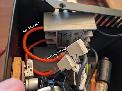
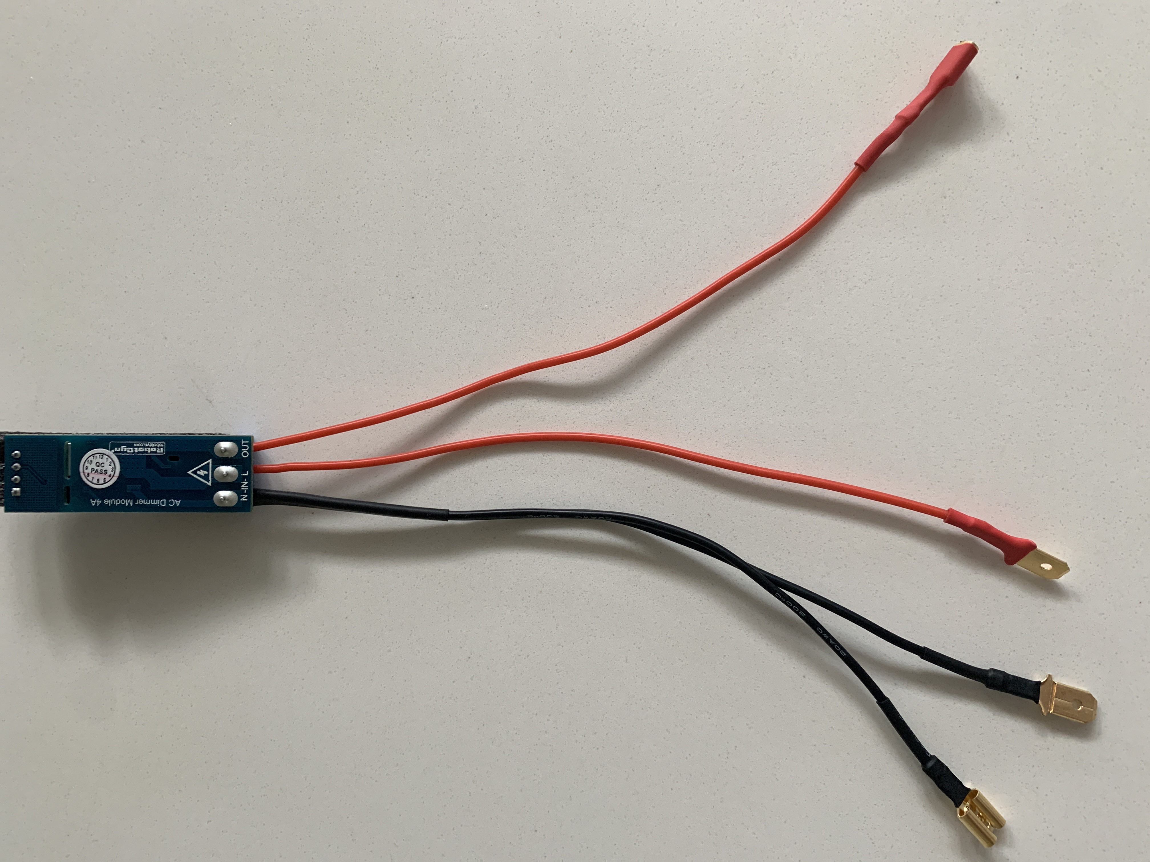
Prepare splitter cables with the below specs:
- Black splitter, 15AWG, 10cm, female end, male end, male end
- Red splitter, 15AWG, 10cm, female end, male end, male end
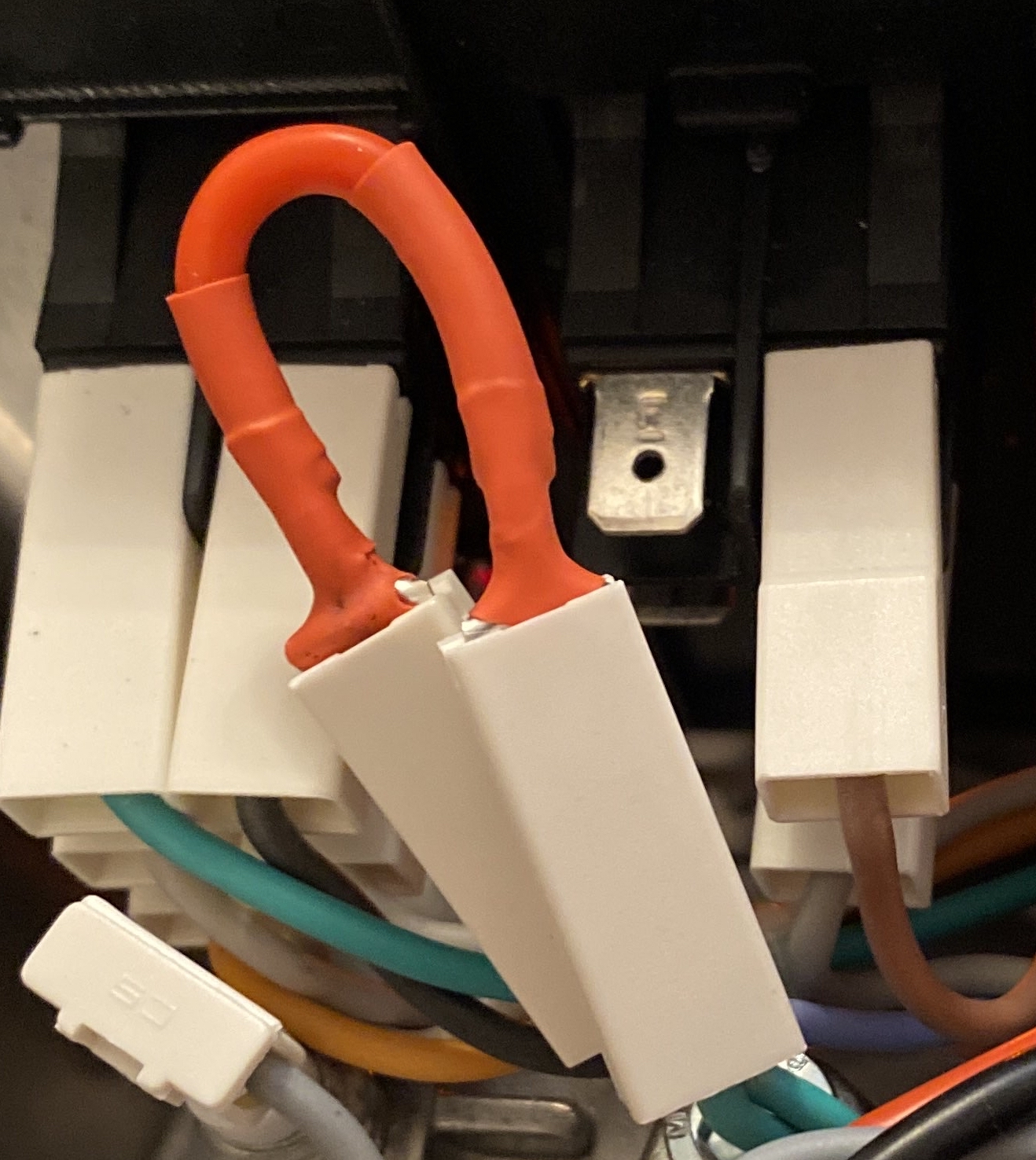
Example of a red and black splitter:
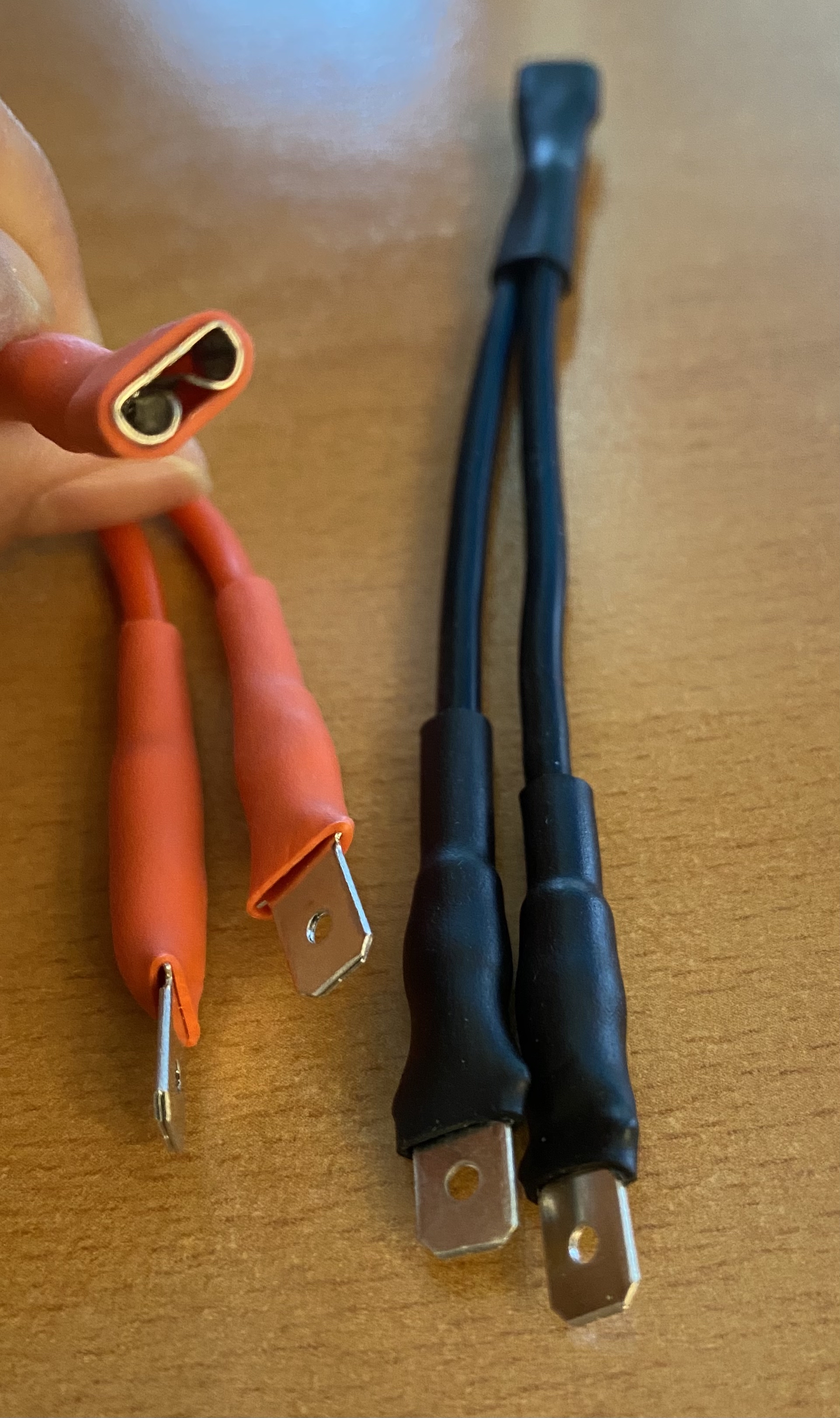
The female end will go in Gaggia's front panel. One male splitter end will go into the connection that came out of the switch position the other male will be for some more wires further down.
Before trying to copy piggyback locations from below it’s recommended to check what the schematics say (3.0.1 Schematics & Diagrams).
By way of context, if looking inside the machine from the back, the left of the power switch is the brew switch. On the power switch - wire in the middle left as LIVE and middle right as GND
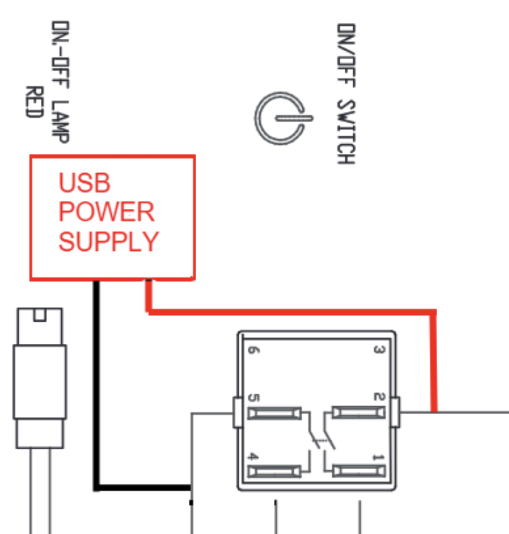
The above translates to the following (please be aware the image below has top connectors removed for clarity):
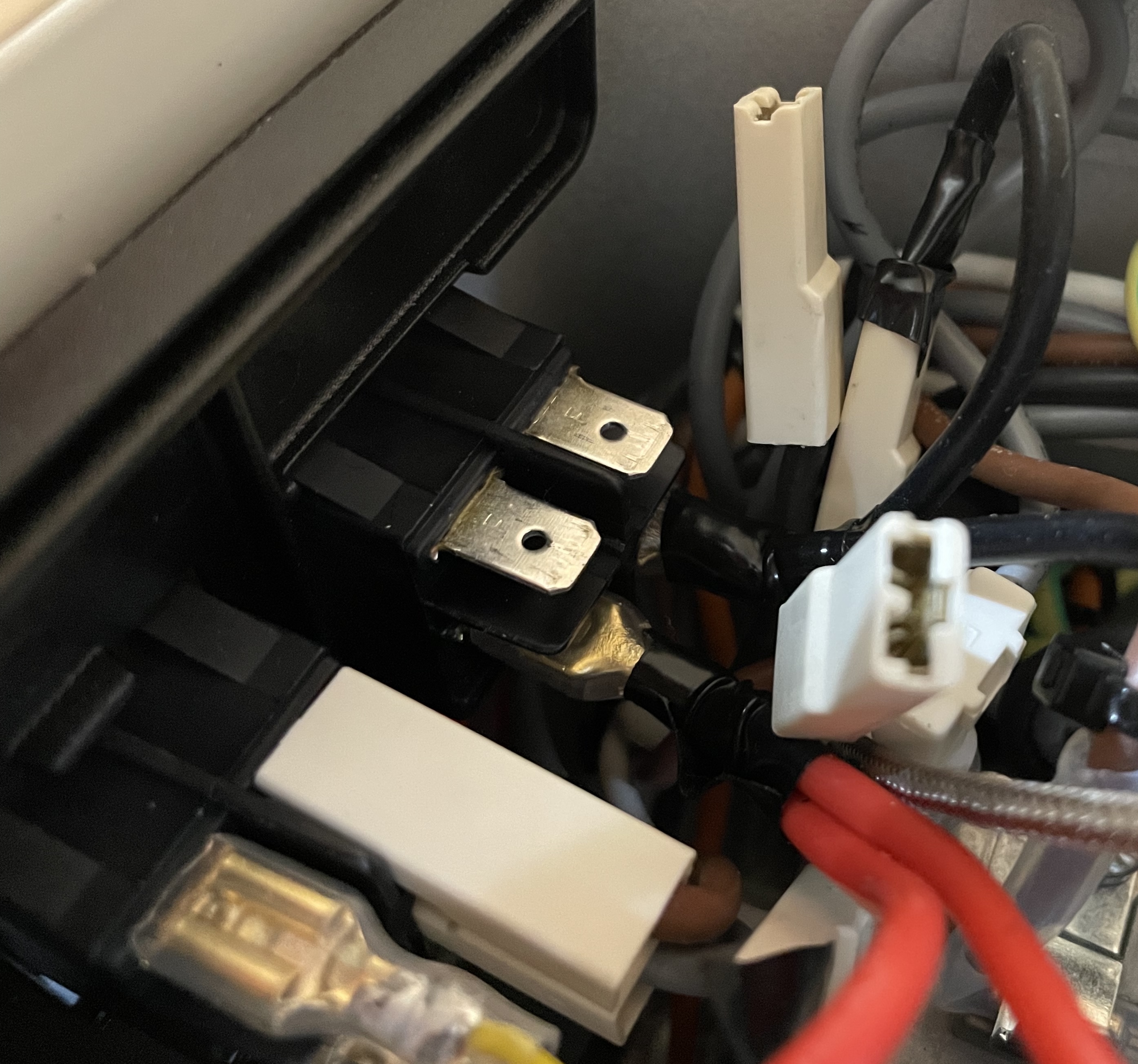
If above standard schematics do not work it can be that your wiring is different. It is recommended to use a multimeter to test.

- Set it to 600V~ (AC) as shown above and test the connectors on the switches
- Just wiggle the connector on the switch out a touch to expose a tiny bit of metal where you put your lead on
- Use schematic to find a GND point
- Your live piggyback will show no voltage until the machine is switched on
As stated you want to find the connector that only shows voltage after flipping the machine machine on.
If your LCD is on even though you've not flipped the machine switch on, this means you've piggybacked into the mains live which is constantly got voltage - this is not correct!
Please see some examples of known differences but really you should be testing with a multimeter.
KNOWN - ECO - EU/UK - piggyback locations non-schematic:

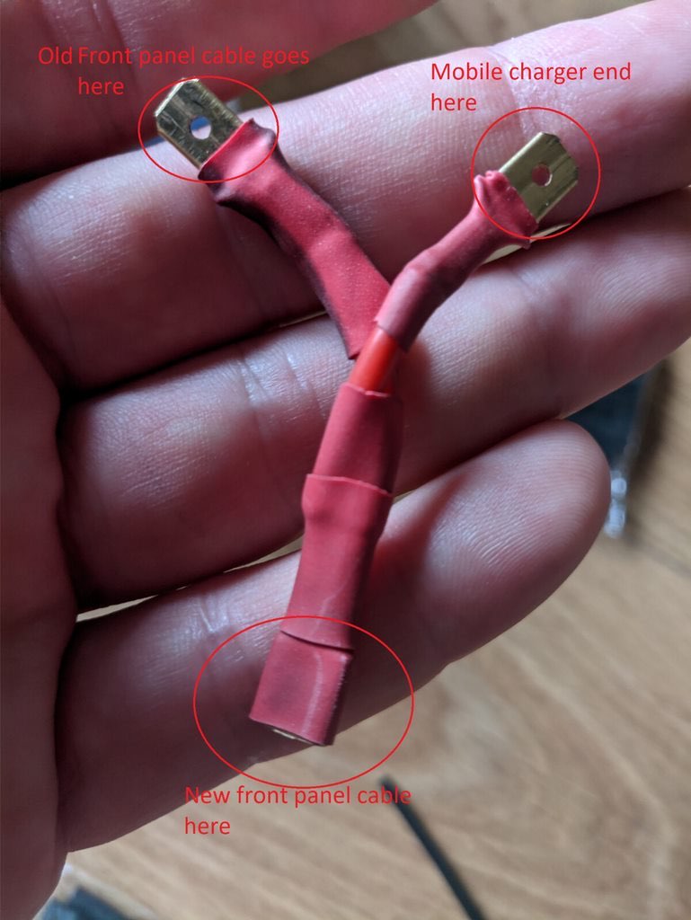
Prepare 2 more cables with the below spec:
- Black, 18/20AWG, about 15cm, female end, exposed end
- Red, 18/20AWG, about 15cm, female end, exposed end
Connect the female end to the male end of the splitter cable from above step (match the colours)
If using the 5v PS - the 2 AC IN ports will be where the exposed end of your red or black piggyback cable go, it doesn't matter which way round (yes, you need to fiddle about getting wires in and solder correctly - recommended to trim, twist, tin and apply heat shrink).
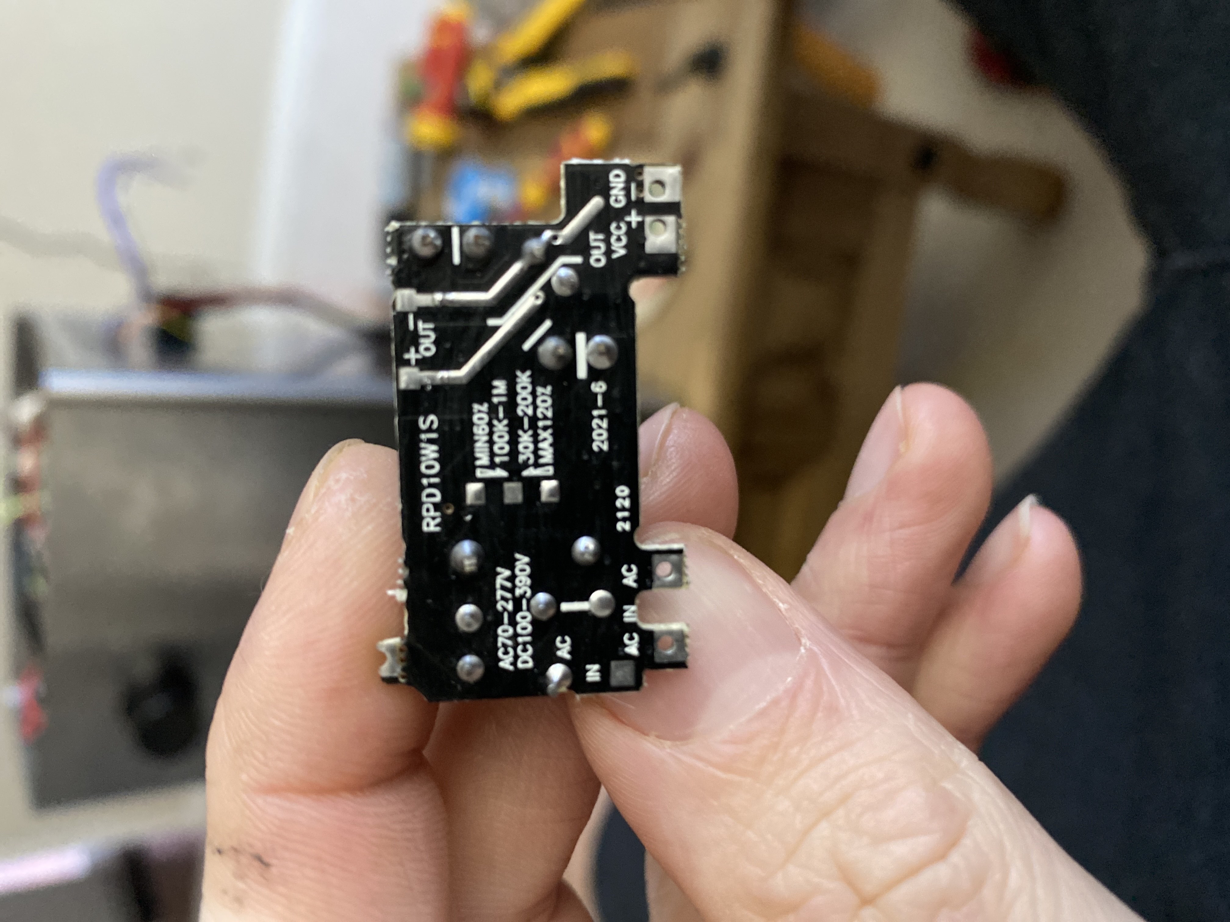
Prepare more cables with the below spec:
- Black, 26AWG, about 25cm, exposed ends
- Red, 26AWG, about 25cm, exposed ends
In relation to the image above - the black will be connected to the GND and the red to the VCC the other ends are going to the Arduino. Please use the tables in 3.0.2 Appendix - Component Wiring for details on wiring VCC and GND connections to the Arduino.
**Make sure this component is well insulated and enclosed. You do not want to touch it or let it make contact with anything whilst the machine is on! **
If you have the ECO version (the machine turns off automatically after 20mins) bridge your brew switch with a 15AWG cable with two male ends, as per below:
Prepare the following cable to the below spec:
- Black, 15AWG, 5cm, two male ends
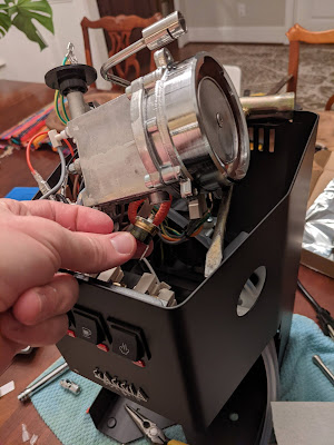
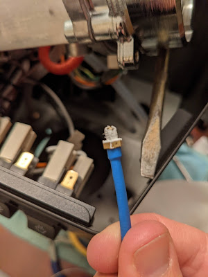
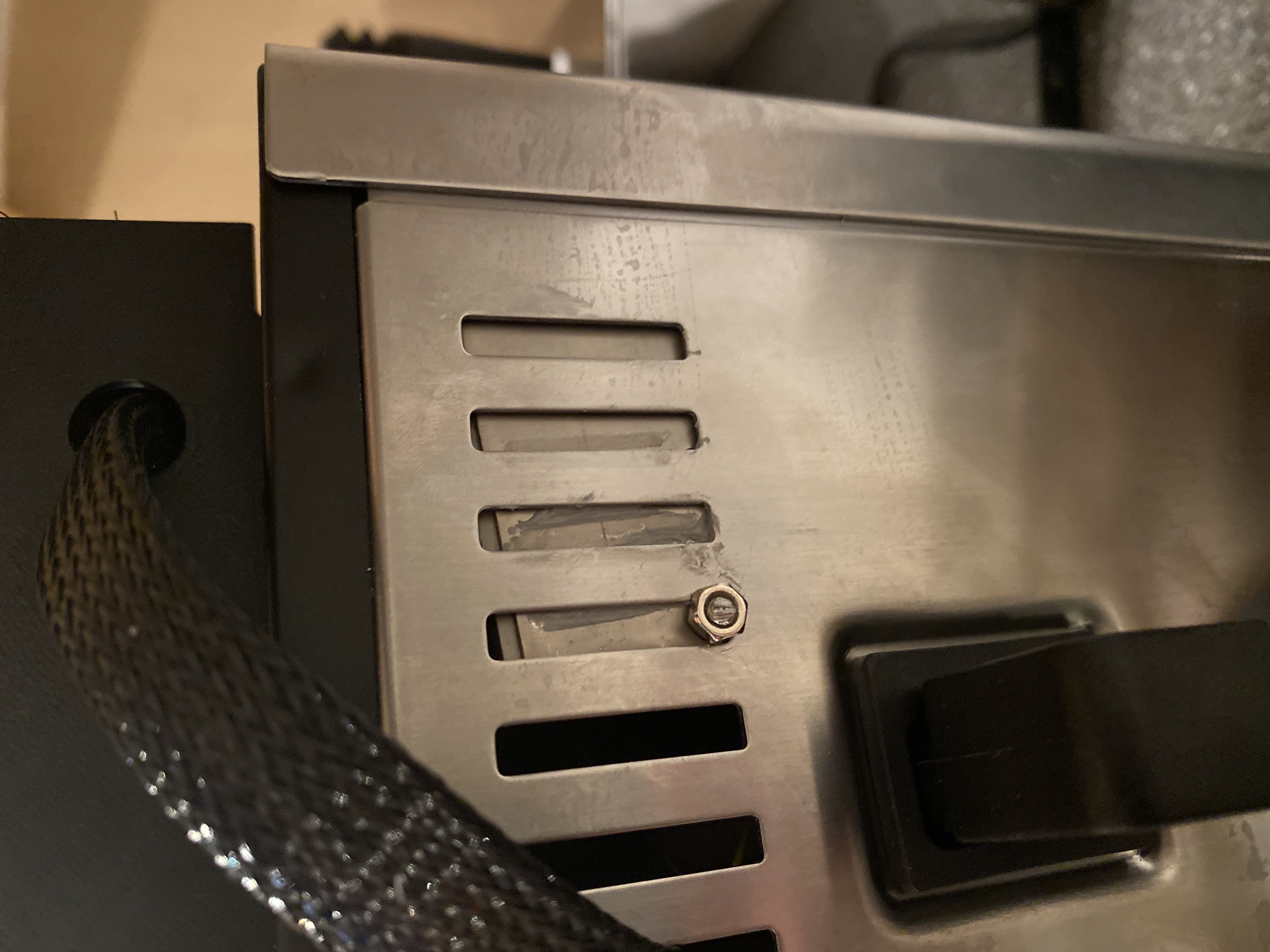
Detach the boiler (only watch as far as the 5min mark) to gain enough access to remove the thermocouple and replace it with the m4 bolted thermocouple sensor.
You’ll obviously need to remove the two connectors from the original thermostat first - which is located at the bottom of the boiler on the side closest to the power on switch.
The small black cable you prepared with the male ends is used to bridge the two wires that you just disconnected from the brew thermostat.
Now unscrew the original thermostat and replace with the m4 brass thermocouple. Be sure to apply some thermal paste (just a teeny tiny bit) on the threads only. It is important to barely tighten the m4 bolt at barely fingertip strength.
Now re-attach the boiler. Check the appendix section ## 3.0.2 Component Wiring 2. MAX6675 WIRING
Make sure this component is well insulated and enclosed. You do not want to touch it or let it make contact with anything whilst the machine is on!
Prepare cables with below spec:
- Red, 15AWG, 10cm, one male end, one exposed end
- Red, 15AWG, 10cm, one male end, one exposed end
The 2 are used to connect the steam thermostat connections to port 1 and 2 of the SSR relay, so:

Optional: might be a good idea to either tape up the exposed steam thermostat or remove it and tape up the exposed location.
Please use the tables in 3.0.2 Appendix - Component Wiring for details on 3 & 4 connections to the Arduino.
Very important to not turn on the machine until we check the steam switch wire positions
NON-ECO VERSION
Image of the steam switch schematic:
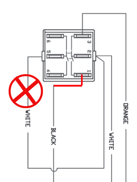
- Move steam switch wire 4 to steam switch pole 1.
- Unplug and secure steam switch wire 5.
- Connect steam switch poles 4 and 5 to the Arduino nano as shown in 3.0.2 Component Wiring - 5. STEAM HANDLING WIRING, using 26AWG wires.
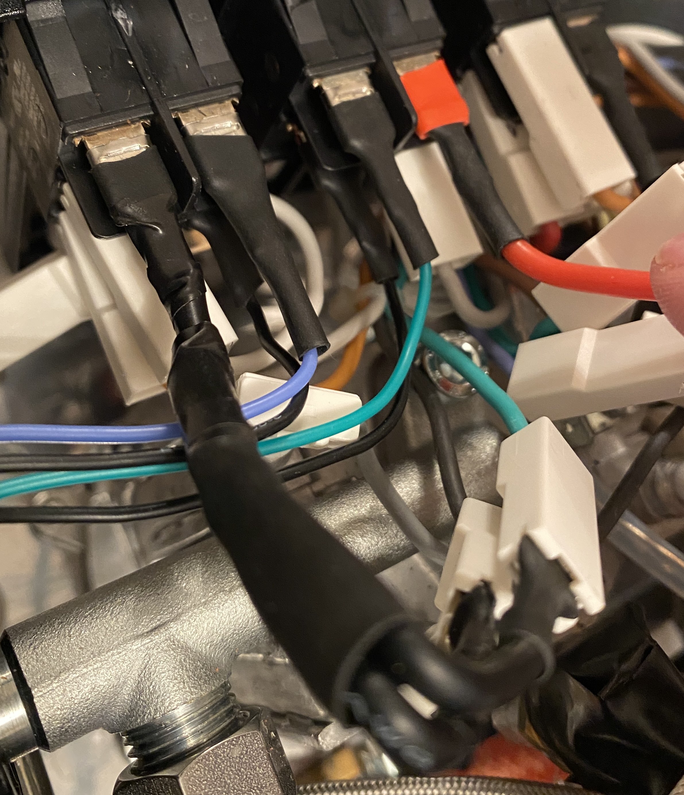
ECO VERSION
Prepare a black splitter with below spec:
-
Black splitter, 15AWG, 5cm, two male ends and one female end
-
Disconnect the two top poles (1 & 4)
-
Use the splitter to bridge the connections you just removed and plug the female into pole 1
-
The connector with two white wires is not on the side of the orange wire (which is at the bottom) then make it so (to match schematics) - i.e move pole 5 connector into pole 2's location (should be two white wires going into the connector)
-
Leave the single white wire disconnected which was in pole 2's location
-
Connect steam switch poles 4 and 5 to the Arduino nano as shown in 3.0.2 Component Wiring - 5. STEAM HANDLING WIRING, using 26AWG wires.
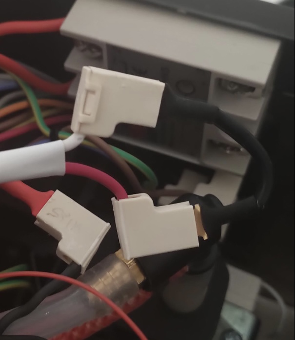
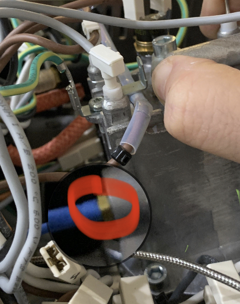
Image for reference below:
Prepare 2 cables with the below spec:
- Green (not red or black), 26AWG, length from brew to Arduino, one exposed end, one female end
- Black, 26AWG, length from brew to Arduino, one exposed end, one female end
As shown below plug your cables in to the circled connections on the brew switch
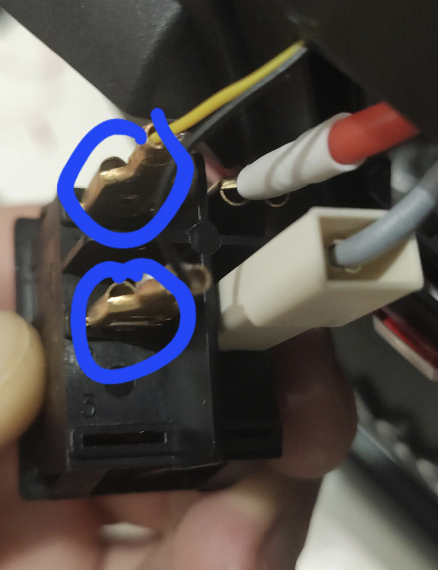
Please use the tables in 3.0.2 Appendix - Component Wiring for details on GND and OUT connections to the Arduino.
Prepare 3 cables with the below spec:
- Red, 18/20AWG, 15cm, one exposed end, one female end
- Red, 18/20AWG, 15cm, one exposed end, one male end
- Black splitter, 18/20AWG, 15cm, one exposed end, one male end, one female end
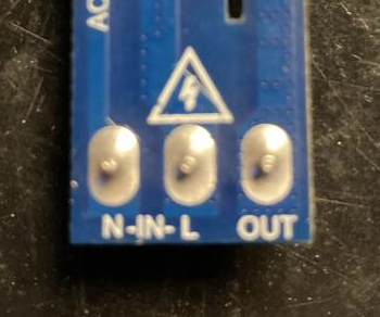
Please check whether your dimmer ports placement in the case it differs from the images before connecting the dimmer, it's very important to feed the IN and OUT wires correctly!
Example of dimmer ports:
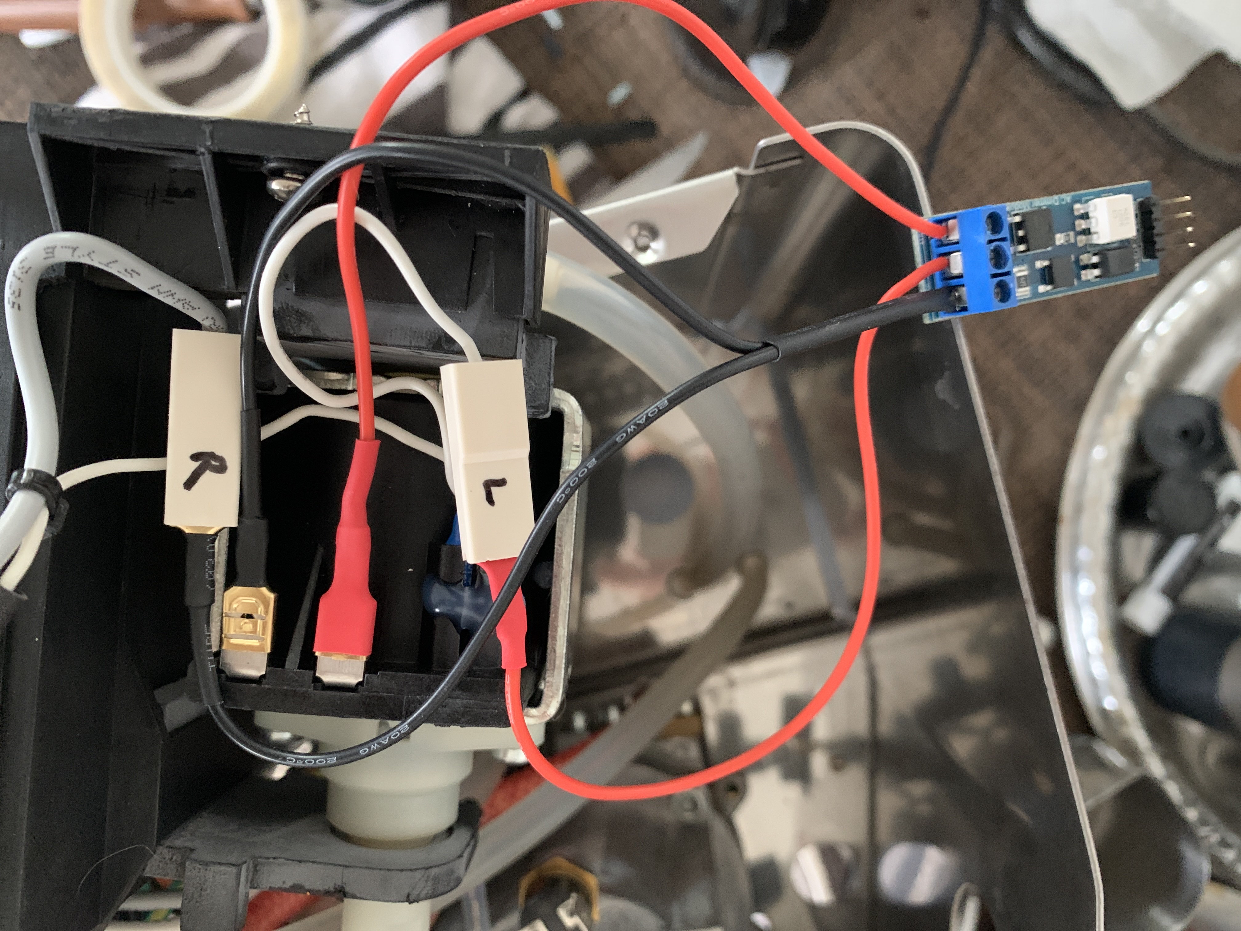
Remove the connections detailed in the image below from the pump (mark the connector either L or R for where it was located either left or right in relation to the pump):-
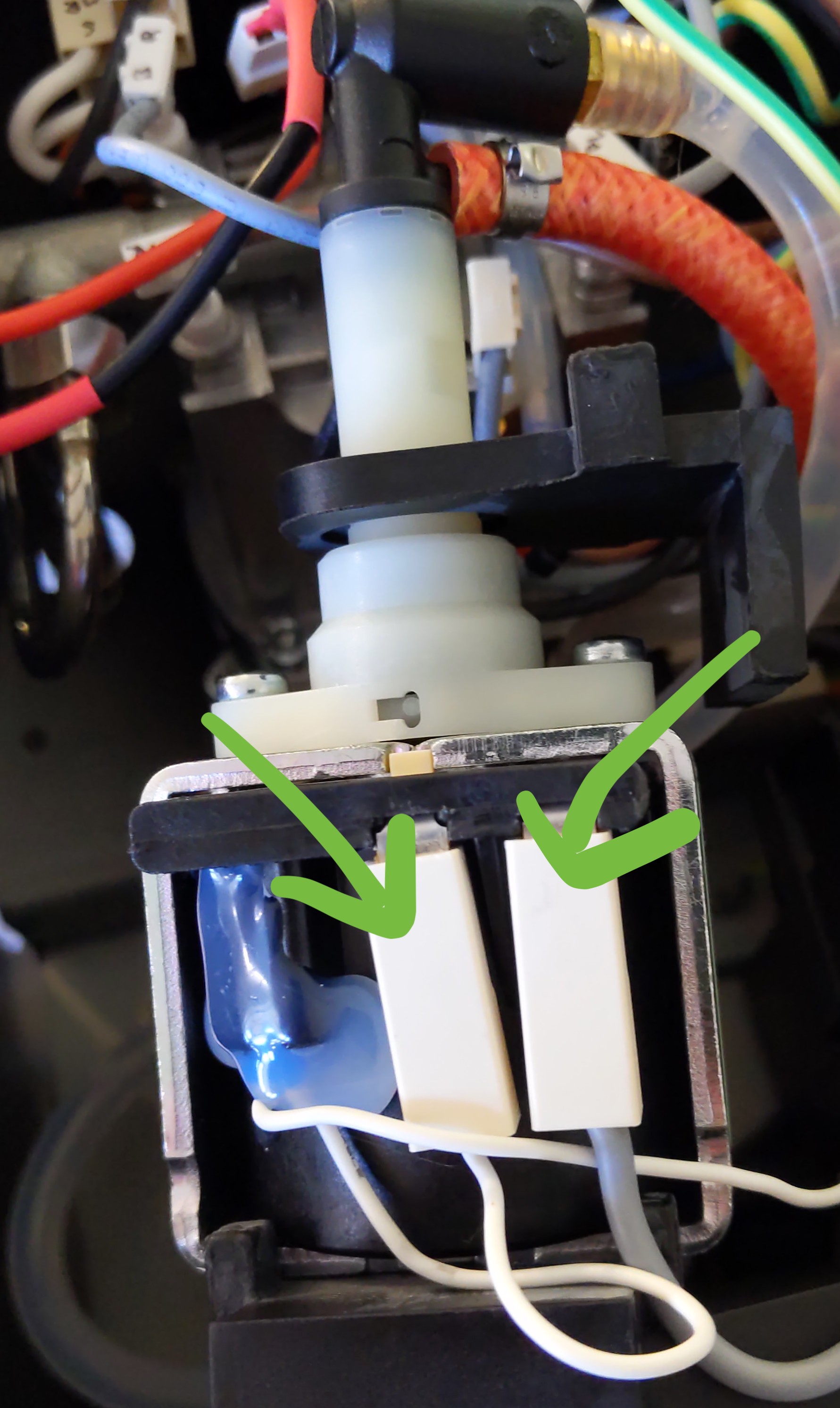
With the cables you prepared:
-
Cable 1: From the dimmer positive line Out - single red wire with the female end going into one of (choose the left connection according to the image above) the pump connections itself.
-
Cable 2: From the dimmer positive line In - single red wire with the male end going into the connector that was removed from the pump above (in this case it would be the left connector).
-
Cable 3: From the dimmer neutral line In - with the black splitter with the male into the connector taken out of the pump (right connector) and female into the (right) remaining connection on the pump itself.
Triple check your dimmer board on what is marked as IN and OUT. 100% need to make sure they are connected properly.
Again!!! Make sure this component is well insulated and enclosed. You do not want to touch it or let it make contact with anything whilst the machine is on!
Please use the tables in 3.0.2 Appendix - Component Wiring for details on VCC, GND, Z-C and PSM connections to the Arduino.
Installing the pressure transducer. The pressure sensor will be tapping into the orange braided hose connecting the pump outlet and the boiler inlet. I would generally advise to take out the original hose and use the one ordered together with the pressure sensor, cut a similarly sized one out of the hose purchased and use the rest of the left length as additional transducer buffer.
It's advisable after making the connections and just before connecting the transducer itself turn on the machine and while cold engage the pump to fill the transducer hose with water as well, leaving a lot of air in the system might play funny with the readings (please be careful to do this outside the machine as water spill out...).
(INSERT IMAGES - of pressure transducer set up)
Please use the tables in 3.0.2 Appendix - Component Wiring for details on RED, BLACK andYELLOW wire connections to the Arduino.
TO DO
If you haven't already, you're ready to connect everything to the Arduino. Use 3.0.2 Appendix for Component Wiring tables.
One piece of advice would be to solder all cables to their respective boards as during the machine operation there is quite a bit of vibration which can introduce noise/frequent. This can lead to unexplained behaviours.
Any components sitting next to each other can have their equivalent pins linked with a cable.
You will be expected to solder similar pins i.e. GND and 5v together in order to fit into and screw down on the expansion board terminals.
On first start up record and send to #first-start channel of discord. This helps with diagnosing issues.
Remember to change and save your correct region settings.
Configure you PP and PI settings and get prepped for a shot if all is well. Record and upload to #first-shot on the discord.
All going well, feel like an absolute coffee titan each and every time you pull a shot.
You can find the defined pins at the top of the .ino file.
A suggestion on wiring; components that are inside same enclosure, the same connection can be linked i.e. solder a cable to the 5v pin then take the other end and solder to the 5V of the other component, from there take one cable to the Arduino. An alternative way is to solder similar connections and apply heat-shrink before the exit to the machine then take one wire through the machine to the Arduino.
- POWER DELIVERY RECOMMENDATION Method 1 - If choosing to power the system using the AC adapter then the Arduino board and all the connected components will receive power by the means of the regulated 5v the AC adapter delivers through the USB port.
| PS | Arduino |
|---|---|
| VCC OUT | 5v |
| GND OUT | GND |
Method 2 - If powering using the [ 12v ] power supply module + [ 9v ] step-down convertor follow the bellow scheme:
| PS | Arduino |
|---|---|
| 9v | VIN |
| GND | GND |
All the other boards below will get their power from the Arduino 5v / GND pins and it's extremely important they are powered using those outputs.
- MAX6675 WIRING
| MAX6675 | Arduino |
|---|---|
| VCC | 5v |
| GND | GND |
| SCK | D6 |
| SO | D4 |
| CS | D5 |
- RELAY WIRING
| RELAY | ARDUINO |
|---|---|
| 4 | GND |
| 3 | D8 |
- NEXTION WIRING
| NEXTION | ARDUINO |
|---|---|
| TX | RX |
| RX | TX |
| VCC | 5v |
| GND | GND |
- STEAM HANDLING WIRING
4 & 5 are the switch points from 2.1.4 Steam Config
| GCP SWITCH | ARDUINO |
|---|---|
| 4 | D7 |
| 5 | GND |
- CONTINUITY WIRING
| BREW SWITCH | ARDUINO |
|---|---|
| TOP | GND |
| BOTTOM | A0 |
- ROBOTDYN DIMMER WIRING
| DIMMER | ARDUINO |
|---|---|
| VCC | 5v |
| GND | GND |
| Z-C | D2 |
| PSM | D9 |
- TRANSDUCER WIRING
| TRANSDUCER | ARDUINO |
|---|---|
| RED | 5v |
| BLACK | GND |
| YELLOW | A1 |
- LOAD CELLS
TO DO
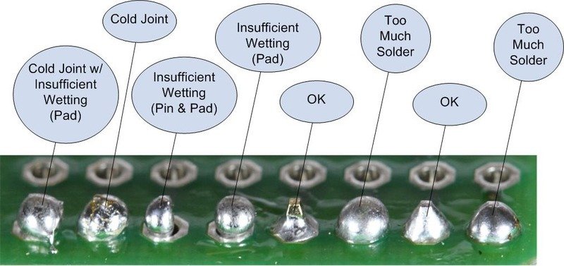
- Take your time soldering perfectly
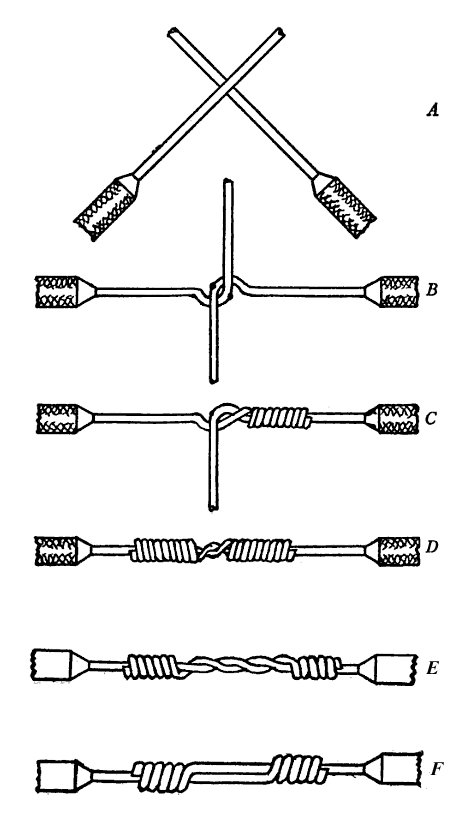
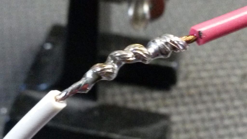
- Use the "Western Union" splice to link wires (GND and 5v)
- Tin your wires to make them easier to solder.
- GitHub: https://github.com/Zer0-bit/gaggiuino
- Discord: https://discord.com/channels/890339612441063494/890339612441063497
- Soldering 1: https://youtu.be/Fb7ONG08BUk
- Soldering 2: https://youtu.be/Fp37DPZVdRI
- Crimping : https://youtu.be/nvPESov0HbY
- Nextion : https://nextion.tech/faq-items/using-nextion-microsd/