CoddsDesign
Codd's 1968 book describes his design for a self-replicating computer in an 8-state CA. This page contains a summary of that design, as recently implemented. You can read a more detailed description in Tim Hutton's paper.
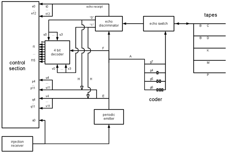
The above image shows an overview of the components in Codd's machine. Letters beside wires indicate where those wires are gated. After initialization from the injection receiver, the periodic emitter sends regular pulses to the echo discriminator and other controls. These pulses are normally blocked since the gates (A, B, C, D, K, M, P, E, F, H, gi, ti, ui, and vi) are all closed. The control section directs the opening and closing of these gates (along wires not shown), allowing pulses from the periodic emitter to travel through various parts as required: to send commands and sense requests to the tapes, for example, and wait for responses. The echo that returns from the tapes is passed into the echo discriminator that sends a pulse down "0" or "1" depending on the echo's type. These echos can be stored in the 4-bit decoder, if one of u0-u3 or v0-v3 is open. If H is open, the echos can also toggle one of the two 'echo storage' gates leading to control inputs pi and qi that are shown as hollow arrowheads. Every echo also generates an echo receipt. The echo switch simply ensures that signals from the coder head towards the tapes, while signals from the tapes head towards the echo discriminator.
Inside the control section, Codd's 'microprogram' connects the inputs (s0, etc.) to a sequence of gates to be toggled. The microprogram is listed below:
s0: M, x, xr, t12, sw
e12: cs, rr, M, D, B, K, P, xr, P, x, K, B, D, P, H, w4, s4
s4: sw
e4: cs, E
p4: s4
q4: H, w4, rr, M, x, M, xr, P, s3
s3: P, w0, sw
e0: cs, rr, M, x, M, xr, w0, w1, sw
e1: cs, rr, M, x, M, xr, w1, w2, sw
e2: cs, rr, M, x, M, xr, w2, w3, sw
e3: cs, rr, M, x, M, xr, w3, P, F
f1: C, s3
f2: D, s3
f3: s3
f4: B, x, B, s3
f5: B, xl, B, s3
f6: B, xr, B, s3
f7: B, r, B, s3
f8: B, rl, B, s3
f9: B, rr, B, s3
f10: B, m, B, s3
f11: B, e, B, s3
f12: H, w5, B, sw
e5: cs, B, E
p5: w5, w6, P, s6
s6: sw
e6: cs, E
p6: w6, rr, M, x, M, xr, P, H, s3
q6: rr, M, x, M, xr, s6
q5: w5, w7, P, s7
s7: sw
e7: cs, E
p7: w7, rr, M, r, P, xr, w8, s8
q7: P, K, r, rr, x, xr, x, m, K, P, rr, M, x, M, xr, s7
s8: sw
e8: cs, E
p8: rr, P, r, P, xr, s8
q8: w8, rr, r, xr, w9, sw
e9: cs, rr, x, xr, E
p9: w9, w8, p8
q9: w9, M, s10
s10: w10, K, sw
e10: cs, E
p10: K, w10, H, M, rr, M, P, xr, P, s3
q10: e, rr, r, xr, x, K, w10, w11, M, s11
s11: rr, P, x, P, xr, sw
e11: cs, E
p11: s11
q11: w11, M, s10
f13: s3
f14: B, i, B, s3
f15: B, j, B, s3
Where program steps appear on the right (e.g. s4 at the end of the e12 sequence) these indicate the next command to be executed; these are goto commands. Some of those commands were written in an abbreviated form and are expanded as here:
x: G7, G6
xl: G4, G4, G5, G6
xr: G5, G5, G4, G6
r: G4, G5, G6, G6
rl: G5, G6, G6, G6
rr: G4, G6, G6, G6
m: G7, G6, G4, G5, G7, G6
e: G6, G7, G4, G5, G6, G6
i: G7, G5, G6
j: G6, G7, G7, G6, G6
sw: G7, G7
cs: G4, G6
G4: g4, A, g4
G5: g5, A, g5
G6: g6, A, g6
G7: g7, A, g7
w_i: t_i, u_i, v_i
The first 10 are program tape commands, while sw stands for sense-and-wait and cs for cap-after-sense.
- The injection receiver is where the machine is first triggered. It sets the periodic emitter running (emitting 7 signals) and sends a 7 signal along the input s0 to the control section.
- The microprogram tells you that s0 sends the sequence:
M, x, xr, t12, sw - This sequence expands to:
M, g7, A, g7, g6, A, g6, g5, A, g5, g5, A, g5, g4, A, g4, g6, A, g6, t12, g7, A, g7, g7, A, g7. This sequence does the following:- The gate M to the marker tape is opened. (All gates are initially closed.)
- Gate g7 in the coder is opened.
- Gate A is opened. This allows a signal from the periodic emitter to pass through A. Gate A is subordinate-restored; it closes itself when a signal goes through. So A closes after letting exactly one signal through.
- The signal leaves the coder still as type 7, since only gate g7 was open.
- The echo switch sends the 7 signal in the direction of the tapes.
- Only the marker tape (M) has an open gate, so the 7 signal reaches the end of the marker tape wire.
- Gate g7 is closed.
- The sequence
g6, A, g6does the same thing as above, sending a signal of type 6 to the marker tape. The marker tape head has now advanced by one cell. - The sequence 5-5-4-6 (xr) follows; the marker head turns right.
- Gate t12 is opened.
- The next 7 signal exposes the end of the wire for sensing.
- The next 7 signal causes an echo to return from the marker tape, of type 6 or 7 depending whether the bit was 0 or 1. In this case we know that the first bit is 1, so the echo is a type 7 signal.
- The echo switch sends the returning echo in the direction of the echo discriminator.
- The echo discriminator sends a 7 signal down the "1" wire but this is blocked at vi and H since these gates are all closed. The echo discriminator also generates a 7 signal on the 'echo receipt' wire for every echo. Gates t0-t11 are closed too but gate t12 has been opened, so the signal passes onto control input e12.
- The microprogram sequence beginning e12 is now executed. (Gate t12 is subordinate-restored in TJH's implementation - Codd forgot to close this gate.) So you can see that the control section is just wiring - signals from the input wires are branched out onto certain output wires that lead to the gates. These gate-controlling wires aren't shown in the diagram at the top but can be seen in the implementation which you can download and run.
The machine continues to operate as described. Instructions on the program tape P are sampled in blocks of 4 bits and open various gates in the decoder. Upon read-out (the wire past F) the value stored is decoded and a signal emerges on one of the lines f0-f15, as listed below. These 16 lines each correspond to a unique instruction, which give the same power as Wang's W-machine.
f0: (not connected to anything, causes the machine to halt)
f1: toggle gate C
f2: toggle gate D
f3: (no operation (nop); can be used for delaying)
f4: x (sends 7-6 down whichever of C and/or D is open)
f5: xl
f6: xr
f7: r
f8: rl
f9: rr
f10: m (mark)
f11: e (erase)
f12: jump_if_one:k (see below)
f13: nop
f14: i (inject the sheathing signal into the new machine)
f15: j (inject the trigger signal into the new machine)
With the right instructions on the program tape (P) and the data tape (D), the machine is capable of self-replication. One such program is listed below.
# -- first we jump to a subroutine to prepare for tape copying
    c,m,jump_if_one:extendup,
# ----- retract until marker (used for tape *and* construction) ----
retract_until:
    e,xl,x,jump_if_one:done_retract,r,rl,m,jump_if_one:retract_until,
# ---------- data tape copying phase: ------------------------
# == 1 ==
write1:
    r,rr,d,c,xr,m,rr,d,x,c,xr,x,jump_if_one:write1,
# == 0 ==
    r,rr,c,x,c,xr,x,jump_if_one:write1,
# == 00 ==
    r,rr,c,x,c,xr,x,jump_if_one:write1,
# == 000 ==
    r,rr,c,r,r,d,m,jump_if_one:retract_until,
# ---------- construction phase: ------------------------
nextcolumn:
    e,x,c,d,r,xr,x,jump_if_one:1,
# == 0 ==
    r,rr,r,xr,x,jump_if_one:01,
# == 00 ==
    r,rr,r,xr,x,jump_if_one:001,
# == 000 ==
    m,jump_if_one:doneconstructing,
01:
    r,rr,d,
# -- write N 0s --
    c,[x]*N,m,jump_if_one:nextcolumn,
1:
    r,rr,r,xr,x,jump_if_one:11,
# == 10 ==
    r,rr,d,c,x,m,jump_if_one:nextcolumn,
11:
    r,rr,d,c,xr,m,rr,x,m,jump_if_one:nextcolumn,
001:
    r,rr,d,c,m,jump_if_one:retract_until,
# ------------------------ subroutines (here for speed): -----------------
retractcolumn:    # retract vertically after construction
    e,xl,x,jump_if_one:inject,r,rl,m,jump_if_one:retractcolumn,
done_retract:     # after retraction: decide whether was tape copying or construction row
    e,rl,r,xl,x,jump_if_one:retractdown,r,rl,r,r,rr,x,xr,x,x,x,xl,x,m,r,rl,m,jump_if_one:nextcolumn,
extendup:         # extend the C-arm up to copy the tape
    e,xl,x,x,x,x,x,x,x,x,x,x,x,x,x,x,x,x,x,x,x,x,x,x,x,x,x,
    xr,[x]*(X-3),xl,[x]*(Y+6),xr,x,x,x,xl,x,m,r,rl,x,xl,x,m,r,rl,
    c,d,jump_if_one:write1,
retractdown:      # pull the C-arm down after copying the tape
    e,rl,r,r,r,rr,[r]*(Y+6),rl,[r]*(X-3),rr,x,x,x,x,x,x,x,x,
    xl,x,m,r,rl,xr,x,x,x,xl,x,m,r,rl,m,jump_if_one:nextcolumn,
doneconstructing: # end of construction: prepare to retract vertically
    e,x,d,c,xl,x,e,rl,r,r,r,rr,m,jump_if_one:retractcolumn,
inject:           # done retracting vertically: sheath, trigger, retract and stop
    e,rl,r,r,xr,x,i,j,r,r,rr,r,r,r,stop
This program is compiled down to a binary sequence of cells before being written to the program tape (P), with the 4-bit encoding described above. Entries following # are comments. Entries ending in colons are labels, as jump destinations, and are replaced by command numbering in the final program - the jump_if_one command (1100 = f12) is followed by a unary encoding of the index of the program command (k) to jump to: a string of k ones followed by a zero. Three parameters are used: N=15 is defined below, while X=22252 and Y=4189 contain the position of the data tape of the new machine, relative to its bottom-left corner.
The data tape contains an encoding of the body of the machine:
11: write a 1
10: write a 0
01: write N 0's
001: end of row
000: end of construction
Where N is used for compression of empty areas. The value of N=15 was chosen because that gave the shortest data tape.
The program first copies D, then decodes it to construct the new machine's body. Finally the program sheathes and triggers the new machine, allowing it to replicate in turn.
With other commands on the program tape, the original machine could perform other operations.