showcase of using 3 cameras in 2 machines
There are a couple of reasons why the number of cameras connected to a single computer is limited: CPU usage, USB bandwidth, power supply and also, the length of the USB cable. These are all covered in length in the following white paper: Multiple_Camera_WhitePaper
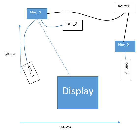
In order to demonstrate the scenario we created the following array:
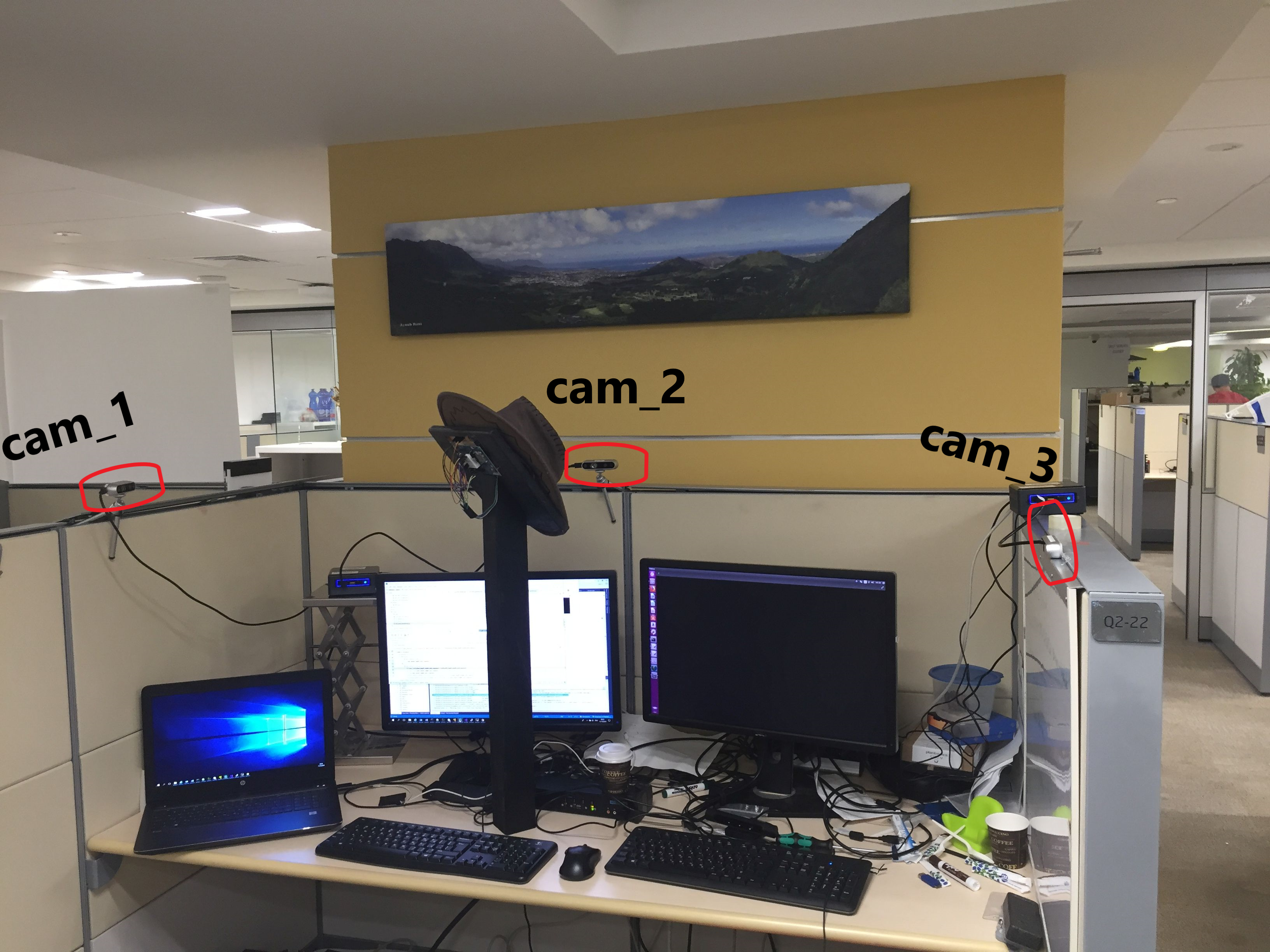
Both cam_2 and cam_3 are visible in cam_1’s point cloud. That way, it’s easier (not easy, mind you) to use set_cams_transforms.py to fix their location in cam_1’s coordinate system. We'll get to that later on.
While using multiple computers we have to specifically set the roscore host. In this demo, the first command in each terminal is:
export ROS_MASTER_URI=http://<ros host ip address>:<port>
In this demo, the roscore, cam_1 and cam_2 run on perclnx319 and cam_3 is on perclnx217.
Also, in this demo all the terminals are being opened on roscore’s computer, perclnx319.
The commands to run are as follows (Don’t forget to replace the serial numbers with your own. Checkout Step 1 in Showcase-of-using-2-cameras for a method of retrieving them):
roscore
export ROS_MASTER_URI=http://perclnx319:11311 roslaunch realsense2_camera rs_camera.launch camera:=cam_1 serial_no:=728312070349 filters:=spatial,temporal,pointcloud
export ROS_MASTER_URI=http://perclnx319:11311 roslaunch realsense2_camera rs_camera.launch camera:=cam_2 serial_no:=713612070696 filters:=spatial,temporal,pointcloud
ssh perclnx217
[Enter Pasword]
export ROS_MASTER_URI=http://perclnx319:11311 roslaunch realsense2_camera rs_camera.launch camera:=cam_3 serial_no:=725112060487 filters:=spatial,temporal,pointcloud
Now we have the topics of pointcloud published.
cam_1 is rotated about 30 degrees compared to the left side of the imaginary square created by the 3 cameras. This camera is our coordinate system.
We estimate the translation of cam_2 from cam_1 at 90(cm) on X-axis and 30(cm) on Y-axis. We also estimate the yaw angle of cam_2 at 120(degrees) clockwise, compared to cam_1. These are the initial parameters we set for the transformation between the 2 cameras.
As for cam_3, we estimate the translation on X-axis at 160(cm) and on Y-axis at -20(cm). We estimate the yaw at 170(degrees) counter-clockwise.
The following script calculates the transformation from the given parameters and publish the frame transform.
cd catkin_ws export ROS_MASTER_URI=http://perclnx319:11311 python src/realsense/realsense2_camera/scripts/set_cams_transforms.py cam_1_link cam_2_link 0.9 0.3 0 -120 0 0 --file ‘_cams_set_info_1_to_2’
Press Q to Quit.
Now set transformation for cam_3:
python src/realsense/realsense2_camera/scripts/set_cams_transforms.py cam_1_link cam_3_link 1.6 -0.2 0 170 0 0 --file ‘_cams_set_info_1_to_3’
Since set_cams_transforms.py is not a ROS-package and you can’t run 2 nodes with the same name, we run 1 copy at a time.
From now on, the last values for the relative transformations are saved in the specified files. If you want to modify cam_2 extrinsic, type:
python src/realsense/realsense2_camera/scripts/set_cams_transforms.py cam_1_link cam_2_link --file ‘_cams_set_info_1_to_2’
To modify cam_3:
python src/realsense/realsense2_camera/scripts/set_cams_transforms.py cam_1_link cam_3_link --file ‘_cams_set_info_1_to_3’
Notice: Use 2 different file names for saving the results for 2 different sets of cameras.
Enter the following command: ' rviz ' In RViz, do the following:
- Set “Fixed Frame” to “cam_1_link”
- Add -> By topic -> /cam_1/depth/color/points/PointCloud2
- Add -> By topic -> /cam_2/depth/color/points/PointCloud2
- Add -> By topic -> /cam_3/depth/color/points/PointCloud2
- Add -> By display type -> TF
- In the “Displays” window under TF > Frames enable only cam_1_link, cam_2_link and cam_3_link. Just for clarity reasons.
Now 3 point clouds are shown together. It’s easy to see that the clouds are not exactly in position. Some features are duplicated. Now it’s time for fine calibration:
Switching to terminal 5, where set_cams_transforms.py is still running, we use it to fine calibrate cam_2 and cam_3 relative to cam_1. The instruction are printed by the program:
`
Using file /home/doronhi/catkin_ws/_cams_set_info_1_to_3.txt
Read initial values from file.
Press the following keys to change mode: x, y, z, (a)zimuth, (p)itch, (r)oll For each mode, press 6 to increase by step and 4 to decrease Press + to multiply step by 2 or - to divide
Press Q to quit ` Without an automatic calibration tool I found it quite a challenge to tune the cameras. Here are a couple of pointers that served me:
- Calibrate 1 camera at a time.
- Set cam_2 in the field view of cam_1. Keep in RViz display only the pointcloud of cam_1 and the axis notation (TF) of cam_2. Now it’s possible to watch the axis notation of cam_2 and change its x,y,z parameters until it’s located right on top of the camera as seen in cam_1’s pointcloud. You can even try and put some distinct object close by and directly in line of sight of cam_2 and try to modify its orientation parameters to align the axis image so it will point to the object as seen in cam_1’s pointcloud.
- Now, display also the pointcloud of cam_2. Put a board to be seen by both cameras. Modify cam_2’s parameters to rotate the board until it is aligned parallel to the board as seen from cam_1, then translate it, rotate again and so on, iteratively, until they are exactly aligned. I use the board to understand what parameter to modify and my face for fine tuning.
- Repeat step 2 and 3 for cam_3 as well.
Eventually, I was relatively satisfied with the following numbers:
for cam_2:
| Parameter | Value |
|---|---|
| x | 0.95 |
| y | 0.38125 |
| z | -0.015625 |
| azimuth | -104.25 |
| pitch | 0 |
| roll | -0.5 |
for cam_3:
| Parameter | Value |
|---|---|
| x | 1.5875 |
| y | -0.703125 |
| z | -0.05 |
| azimuth | 163 |
| pitch | 1 |
| roll | 1.25 |
No doubt, a SLAM based solution is better then the manual labor I've been through to get this calibration, both in time and results. Nevertheless, the final 3D-model I got looked like that:
