gantt
    title MCUBootUtility Release Plan
    dateFormat  YYYY-MM-DD
    section Formal Release
    v1.0.0           :a1, 2018-08-27, 2018-12-28
    v1.1.0           :a2, 2018-12-29, 2019-01-29
    v1.2.0           :a3, 2019-01-30, 2019-04-16
    v1.3.0           :a4, 2019-04-17, 2019-04-29
    v1.4.0           :a5, 2019-04-30, 2019-05-09
    v2.0.0           :a6, 2019-05-10, 2019-07-19
    v2.1.0           :a7, 2019-07-20, 2019-12-03
    v2.2.0           :a8, 2019-12-04, 2019-12-13
    v2.3.0           :a9, 2019-12-14, 2020-05-28
    v2.4.0           :a10, 2020-08-20, 2020-10-20
    v3.0.0           :a11, 2020-10-21, 2021-01-10
    v3.1.0           :a12, 2021-01-11, 2021-01-13
    v3.2.0           :a13, 2021-01-16, 2021-03-17
    v3.3.0           :a14, 2021-03-18, 2021-05-20
    v3.4.0           :a15, 2021-08-03, 2021-09-27
    v3.5.0           :a16, 2021-09-28, 2022-03-19
    v4.0.0           :a17, 2022-03-20, 2023-01-06
    v4.1.0           :a18, 2023-01-07, 2023-03-02
    v5.0.0           :a19, 2023-04-07, 2023-05-23
    v5.1.0           :a20, 2023-05-24, 2023-05-25
    v5.2.0           :a21, 2023-05-26, 2023-07-07
    v5.3.0           :a22, 2023-07-15, 2023-09-14
    v6.0.0           :a23, 2023-09-15, 2023-11-03
    v6.1.0           :a24, 2023-11-04, 2023-12-19
    v6.2.0           :a24, 2023-12-20, 2024-03-26


English | 中文
对于MCUBootUtility,MCUBootFlasher(RT-Flash)工具,有任何使用上的问题,可以在《痞子衡嵌入式》博客下留言,也可以扫码加入QQ交流群。

NXP-MCUBootUtility is a GUI tool specially designed for NXP MCU secure boot. Its features correspond to the BootROM function in NXP MCU. Currently, it mainly supports i.MXRT, LPC, Kinetis series MCU chips, Compared to NXP official security enablement toolset (OpenSSL, CST, sdphost, blhost, elftosb, BD, MfgTool2), NXP-MCUBootUtility is a real one-stop tool, a tool that includes all the features of NXP's official security enablement toolset, and what's more, it supports full graphical user interface operation. With NXP-MCUBootUtility, you can easily get started with NXP MCU secure boot.
The main features of NXP-MCUBootUtility include:
- Support both UART and USB-HID serial downloader modes
- Support various user application image file formats (elf/axf/srec/hex/bin)
- Can validate the range and applicability of user application image
- Support for converting bare image into bootable image
- Support for loading bootable image into external boot devices
- Support common boot device memory operation (Flash Programmer)
- Support i.MXRT1011, i.MXRT1015, i.MXRT1021, i.MXRT1024 SIP, i.MXRT1042, i.MXRT105x, i.MXRT106x, i.MXRT1064 SIP, i.MXRT116x, i.MXRT117x, i.MXRT118x
- User image file can be either bare image file or bootable image file
- Support for converting bare image into .sb file for MfgTool and RT-Flash
- Support for loading bootable image into FlexSPI NOR boot device
- Support for loading bootable image into FlexSPI NAND boot device
- Support for loading bootable image into SEMC NAND boot device
- Support for loading bootable image into SEMC NOR boot device
- Support for loading bootable image into uSDHC SD/eMMC boot device
- Support for loading bootable image into LPSPI NOR/EEPROM recovery boot device
- Support DCD which can help configure device (eg. SDRAM)
- Support XMCD which can help configure FlexSPI RAM/SEMC SDRAM
- Support development boot case (Unsigned)
- Support HAB encryption secure boot case (Signed only, Signed and Encrypted)
- Can back up certificate with time stamp
- Support BEE encryption secure boot case (SNVS Key, User Keys)
- Support OTFAD encryption secure boot case (SNVS Key, User Keys)
- Support common eFuse memory operation (eFuse Programmer)
- Support common FlexRAM memory operation (ISP Boot)
- Support for reading back and marking bootable image(NFCB/DBBT/FDCB/EKIB/EPRDB/IVT/Boot Data/DCD/XMCD/Image/CSF/DEK KeyBlob) from boot device
- Support i.MXRT5xx, i.MXRT6xx, RW61x, i.MXRT7xx
- Support for loading bootable image into FlexSPI/QuadSPI NOR boot device
- Support for loading bootable image into uSDHC SD/eMMC boot device
- Support for loading bootable image into Flexcomm SPI NOR recovery boot device
- Support development boot case (Unsigned, CRC)
- Support common OTP memory operation (OTP Programmer)
- Support common SRAM memory operation (ISP Boot)
- Support for reading back and marking bootable image(OTFAD KeyBlob/FDCB/KeyStore/Image) from boot device
- Support LPC550x/S0x, LPC551x/S1x, LPC552x/S2x, LPC55S6x, LPC553x/S3x
- Support for loading bootable image into C040HD Flash
- Support development boot case (Unsigned)
- Support 2nd gen Kinetis Series (With BootROM, eg: MKL03Z, MK8xF)
- Support for loading bootable image into FTFx Flash
- Support development boot case (Unsigned)
- Support MCXN54x, MCXN94x
- Support for loading bootable image into C040HD Flash
- Support development boot case (Unsigned)
NXP-MCUBootUtility is developed in Python, and it is open source. The development environment is Python 2.7.15 (32bit), wxPython 4.0.3, pySerial 3.4, pywinusb 0.4.2, bincopy 15.0.0, PyAudio 0.2.11, PyInstaller 3.3.1 (or higher).
- Source code: https://github.com/JayHeng/NXP-MCUBootUtility
- Feedback: https://www.cnblogs.com/henjay724/p/10159925.html
NXP-MCUBootUtility is packaged by PyInstaller, all Python dependencies have been packaged into an executable file (\NXP-MCUBootUtility\bin\NXP-MCUBootUtility.exe), so if you do not want to develop NXP-MCUBootUtility for new feature, there is no need to install any Python software or related libraries.
Note1: Before using NXP-MCUBootUtility, you need to download HAB Code Signing Tool from NXP website,upzip it and put it in the \NXP-MCUBootUtility\tools\cst\ directory, then modify the code to enable AES function and rebuild \NXP-MCUBootUtility\tools\cst\mingw32\bin\cst.exe, or HAB related encryption function can not be used properly。See more details in 《The step-by-step guide to rebuild cst.exe for HAB encryption》
Note2: Before using NXP-MCUBootUtility, you need to rebuild the source in \NXP-MCUBootUtility\tools\image_enc\code directory to generate image_enc.exe and put it in \NXP-MCUBootUtility\tools\image_enc\win directory, or BEE/OTFAD related encryption function can not be used properly。See more details in 《The step-by-step guide to build image_enc.exe for BEE/OTFAD encryption》
Note3: The NXP-MCUBootUtility.exe in the source code package is packaged in the Windows 10 x64 environment and has only been tested in this environment. If it cannot be used directly for system environment reasons, you need to install Python2.7.15 x86 version (Confirm that the directory "\Python27" and "\Python27\Scripts" are in the system environment variable path after the installation is completed), then click on "do_setup_by_pip.bat" in the "\NXP-MCUBootUtility\env" directory to install the Python library on which NXP-MCUBootUtility depends. Finally, click "do_pack_by_pyinstaller.bat" to regenerate the NXP-MCUBootUtility.exe.
Note4: You must use Python2 x86 version, because NXP-MCUBootUtility uses the pywinusb library, which cannot be packaged by PyInstaller in Python2 x64 version. The pywinusb author has no plan to fix the problem.
Note5: You cannot make any frequency adjustments in the encrypted code area, if your code includes calling of BOARD_BootClockRUN or any other frequency adjustment function, you should allocate those functions and the function called inside into non encrypted code area.
NXP-MCUBootUtility is a pure green free installation tool. After downloading the source code package, double-click "\NXP-MCUBootUtility\bin\NXP-MCUBootUtility.exe" to use it. No additional software is required.
Before the NXP-MCUBootUtility.exe graphical interface is displayed, a console window will pop up first. The console will work along with the NXP-MCUBootUtility.exe graphical interface. The console is mainly for the purpose of showing error information of NXP-MCUBootUtility.exe. At present, NXP-MCUBootUtility is still in development stage, and the console will be removed when the NXP-MCUBootUtility is fully validated.
The NXP-MCUBootUtility software directory is organized as follows:
\NXP-MCUBootUtility
                \apps                 --Place example source image files
                \bin                  --Place NXP-MCUBootUtility.exe and user configuration file
                \doc                  --Place reference documents related to NXP MCU Boot
                \env                  --Place scripts to install the NXP-MCUBootUtility development environment and to do package
                \gen                  --Place temporary files generated during the use of NXP-MCUBootUtility
                      \bd_file            -- Generated BD files based on configuration
                      \bee_crypto         -- Generated BEE encryption related files
                      \bootable_image     -- Generated bootable image file
                      \dcd_file           -- Generated DCD data file
                      \fdcb_file          -- Generated FDCB file based on configuration
                      \hab_cert           -- Generated HAB signature related files
                      \hab_crypto         -- Generated HAB encryption related files
                      \json_file          -- Generated JSON files based on configuration
                      \log_file           -- Saved software operation log
                      \otfad_crypto       -- Generated OTFAD encryption related files
                      \sb_image           -- Generated .sb file
                      \user_file          -- Temporary files
                \gui                  --Place NXP-MCUBootUtility development UI build project file
                \img                  --Place the image to be loaded during the use of NXP-MCUBootUtility
                \src                  --Place all Python source code files for developing NXP-MCUBootUtility
                \tools                --Place all external programs to be called during the use of NXP-MCUBootUtility
                      \blhost             -- Host command line tool to communicate with Flashloader
                      \cst                -- HAB encryption command line tool
                      \elftosb            -- Command line tool to generate bootable image
                      \ide_utils          -- Command line tool to convert image format
                      \image_enc          -- BEE encryption command line tool
                      \imgutil            -- Command line tool to generate DCD data
                      \openssl            -- Standard tool to generate certificates and keys
                      \sdphost            -- Host command line tool to communicate with ROM
The following figure shows the main interface of the NXP-MCUBootUtility tool. The interface consists of six parts. The functions of each part are as follows:

- [Menu Bar]: Functional menu bar, providing general software settings.
- [Target Setup]: Target device setting bar, providing MCU Device and Boot Device configuration options.
- [Port Setup]: In the serial interface setting field, select the interface for connecting to the MCU Device.
- [Device Status]: The target device status information field is used to display the status of the target device after connecting to the target device.
- [Secure Boot Action]: Secure boot main interface, providing all operations for encrypting the target device.
- [Log Info]: Operation log bar, recording software operation log
There are two main preparations before using the NXP-MCUBootUtility tool: 1. Prepare the i.MXRT hardware board and the serial download cable (USB/UART). 2. Prepare the source image file for downloading into Flash.
For serial download line connections, you need to check the System Boot chapter of the i.MXRT Reference Manual to ensure that the connected UART/USB pins are specified by the BootROM.
Regarding the source image file preparation, the NXP-MCUBootUtility tool can recognize the images of the five common formats (elf/axf/srec/hex/bin). Note that the source image can be either bare image or bootable image.
Take the NXP official SDK as an example to further explain the generation of the source image file, register and log in to the NXP official website, go to the MCUXpresso SDK Builder page, select the appropriate MCU chip and IDE (take RT1060 chip, IAR IDE as an example) and click Download SDK to get SDK_2.4.0_EVK-MIMXRT1060.zip.
Use IAR to open the \boards\evkmimxrt1060\demo_apps\led_blinky\iar\led_blinky.eww sample application in the SDK package:
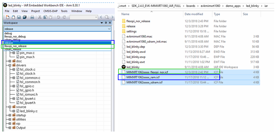
The led_blinky application actually contains three projects (ram/flexspi_nor/sdram), which correspond to three different linker files (.icf). The image generated by the ram project is the so-called Non-XIP image, and the image generated by the flexspi_nor project is so-called XIP image.
By default, the image files generated by the ram project and the flexspi_nor project cannot be used directly by NXP-MCUBootUtility, and some minor changes are required.
You need to modify the linker file for the ram project as follows: (It is recommended to put the link interrupt vector table start from 0x3000, and reserve some memory space in front of the interrupt vector table for placing the file header required for i.MXRT boot).
define symbol m_interrupts_start       = 0x00003000;   // 0x00000000
define symbol m_interrupts_end         = 0x000033FF;   // 0x000003FF

define symbol m_text_start             = 0x00003400;   // 0x00000400
define symbol m_text_end               = 0x0001FFFF;

define symbol m_data_start             = 0x20000000;
define symbol m_data_end               = 0x2001FFFF;

define symbol m_data2_start            = 0x20200000;
define symbol m_data2_end              = 0x202BFFFF;
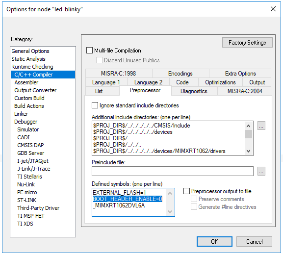
You need to modify the Defined symbols in the project configuration options for the flexspi_nor project as follows: (Set XIP_BOOT_HEADER_ENABLE to 0, It is no need to generate an image containing the i.MXRT boot headers; Keep XIP_BOOT_HEADER_ENABLE as 1, The generated image will contain i.MXRT boot headers).
If you just want to quickly verify the NXP-MCUBootUtility tool, all the led_blinky application image files of NXP's official i.MXRT evaluation boards are stored by default in the NXP-MCUBootUtility\apps folder.
When using NXP-MCUBootUtility, you need to configure the target device. The target device includes MCU Device and Boot Device. Taking the NXP official development board EVK-MIMXRT1060 as an example, the main chip of the development board is i.MXRT1062DVL6A, so [MCU Device] should be set to i.MXRT106x. Taking the most commonly used FlexSPI NOR boot as an example, [Boot Device] is set to FLEXSPI NOR, and the corresponding external memory chip on the development board is IS25WP064AJBLE, which is a commonly used four-wire QSPI NOR Flash, which needs to be further configured. Click the [Boot Device Configuration] button to pop up the following new configuration page:

In the pop-up FlexSPI NOR Device Configuration page, you can see many options describing the Multi-IO SPI NOR Flash feature, such as Device Type, Query Pads, etc. These options need to be set correctly to aligned with the external Flash in the development board.
In addition, there is an option called [Use Typical Device Model] on the page. The NXP-MCUBootUtility pre-defines some commonly used Multi-IO SPI NOR Flash model models, if the external storage chip on the development board happens to be in pre-defined model list, you can select the corresponding model directly in the [Use Typical Device Model] without having to configure it one by one in the Nor Option.
The IS25WP064AJBLE chip on the EVK-MIMXRT1060 development board belongs to the ISSI-IS25LP064A category, so we only need to select ISSI - IS25LP064A in [Use Typical Device Model] and click [Ok] to complete the setting of the target device.
After setting up the target device, the next step is to connect the target device. Taking the USB-HID interface as an example, supply power to the EVK-MIMXRT1060 board, and connect the PC to the J9 port with USB Cable. If everything is going well, you can find new HID device (vid=0x1fc9, pid=0x0135) named HID-compliant vendor-defined device is enumerated. If the HID device is not found, please check the board SW7 DIP switch to set Boot Mode to 2'b01(Serial Downloader mode).

After confirming the existence of the HID device, select USB-HID in [Port Setup], and then directly click the [Connect to ROM] button. The NXP-MCUBootUtility will automatically complete the whole process of connecting the target device (using sdphost to connect to the ROM to obtain some MCU internal register information. Using sdphost to load Flashloader and jump to it, using blhost to connect to Flashloader, get some eFuse information, use blhost to configure boot device and get boot device meomry information), this process takes about 5s, if the target device is connected properly, you can see the indicator LED turns blue, and the [Connect to ROM] button label changes to [Reset Device]. If the target device fails to connect, the indicator LED will turn red and the [Connect to ROM] button label will change to [Reconnect].

After the target device is successfully connected, you can see some useful device status information in the target device status information bar, such as the UUID value of the MCU chip, the HAB status, the important Fuse value related to boot, and the Page/Sector/Block size of the Boot Device.
At first, you should make sure Tools/Generate .sb file option in menu bar is set as "No", after the target device is successfully connected, the core secure boot operation can be started. Before the secure boot operation is started, Let's see the secure boot main interface:

- [Image Generation Sequence]: The image generation window is used to encrypt the source image then generate a bootable image that can be placed in the Boot Device.
- [Image Loading Sequence]: The image download window is used to download the generated bootable image into the Boot Device, and burn the corresponding Fuse value in the MCU (various Key, HAB settings, etc.)
- [eFuse Operation Utility]: The eFuse readback and burning window allows the user to burn custom values into the Fuse Region.
- [Boot Device Memory]: The image readback and annotation display window is used to read back the downloaded Bootable image data from the Boot Device and mark the data components.
- [Secure Boot Type]: Select the secure boot mode, select the desired secure mode (do not enable security, HAB signature only, HAB signature & encryption, BEE encryption).
- [All-In-One Action]: One-stop operation, Actions in the image generation window and the image loading window are automatically executed in sequence.
The first mode is the simplest mode, that is, no security measures are initiated, and it is generally used in the product development and debugging phase.
Select "DEV Unsigned Image Boot" in [Secure Boot Type], and then click the [Browse] button to select a raw image file (using the bare image file generated by the IDE, do not need to include any additional headers required for i.MXRT boot in image file**) H**ead), click the [All-In-One Action] button to complete the bootable image generation and download operations.
Note: If 'Auto-detect image format' option is selected, the source file format is automatically recognized based on the file extension. However, for the axf file generated by MCUXpresso or GCC, it needs to be set to ".out(axf) from MCUXpresso/GCC ARM".

Step4 and Step5 in the above figure are not must-have operations. They are only used to confirm whether the [All-In-One Action] button operation is successful, especially the Step5 operation. You can check the Bootable image composition picture displayed in the image download window.
All operations are correct. Set the Boot Mode to 2'b10(Internal Boot mode) via SW7 DIP switch on the board. The rest remains all 0s. You can see that the unsigned image is executed normally after power-on.
The second mode is the primary security mode, that is, only the image is signed and authenticated, and is generally used in applications where product security is high. The signature authentication is mainly to verify the validity of the image and detect whether the image is abnormally damaged or tampered. If the image is found to be illegal, the MCU will not start executing the image.
Select "HAB Signed Image Boot" in [Secure Boot Type], then enter serial (must be 8 digits) and key_pass (any length character) and click the [Advanced Cert Settings] button to configure all the signature authentication parameters (Refer to NXP CST Tool). Then click the [Browse] button to select an original image file, and finally click the [All-In-One Action] button to complete all operations of bootable image generation and download.

Step5 in the above figure is mainly used to confirm two points: First, whether the HAB status is Closed (Fuse 0x460[31:0] bit1 is 1'b1); Second, whether SRKH is correctly programmed (Fuse 0x580 - 0x5f0, a total of 256bit, that is, the sha-256 algorithm), SRKH is the hash value of the Public RSA Key in the CSF data in the final bootable image, and is used to verify whether the Public RSA Key is legal.
All operations are correct. Set the Boot Mode to 2'b10(Internal Boot mode) via SW7 DIP switch on the board. The rest will remain all 0. When the power is turned back on, you can see that the HAB signed image is executed normally.
Because the HAB status of the MCU chip is already Closed and the SRKH has been burned and cannot be changed, the unauthenticated image cannot be run normally. In the software directory \NXP-MCUBootUtility\tools\cst\crts, the Private RSA Key file is stored in the folder. Please save it properly. If it is lost, the new image will not be properly signed and the HAB authentication will fail to be executed.
The third mode is the intermediate security mode, which is to sign and authenticate the image and HAB level encryption, which is generally used in applications where product security is very high. The signature authentication is mainly to verify the validity of the image, and the encryption can protect the image from being illegally stolen in the external Boot Device. Because the external cryptographic data is stored in the external Boot Device, even if it is illegally acquired, it cannot be easily Cracked, and the encryption is bound to the MCU chip, because the HAB encryption process uses the only Master Secret Key in the MCU's internal SNVS module.
Select "HAB Encrypted Image Boot" in [Secure Boot Type], and then configure all the parameters for signature authentication (if there is a certificate in the local, you can use it without configuration, the software will try to reuse), and then click the [Browse] button to select a raw image file. Finally, click the [All-In-One Action] button to complete all operations of bootable image generation and download.

After the Step6 operation in the above figure, you can see that the image downloaded into Boot Deivce is indeed cipher text. In fact, HAB encryption only supports encrypted image area, and other areas (such as FDCB, IVT, Boot Data, etc.) are not encrypted.
All operations are correct. Set the Boot Mode to 2'b10(Internal Boot mode) via SW7 DIP switch on the board. The rest will remain all 0s. After power-on, you can see that the HAB signed encrypted image is executed normally.
You may be curious, since the image is HAB encrypted, where is the password? How to set it up? In fact, the image encryption operation is completely encapsulated by the HAB encryption tool. The AES-128 algorithm is used by HAB encryption, the corresponding 128-bit AES-128 Key is not user-defined, but the HAB encryption tool automatically generates it randomly, and each AES-128 Key generated by every encryption operation is different, even if you have not replaced the original image. The AES-128 Key is saved in the \NXP-MCUBootUtility\gen\hab_crypto\hab_dek.bin file.
From the above diagram, the Bootable image shown in the image download window shows that compared to the HAB single-signature method, the final part of the Bootable image is a DEK KeyBlob component. This DEK KeyBlob is the key data in hab_dek.bin is dynamically encrypted by the Master Secret Key in the internal SNVS module of the MCU chip. Because the Master Secret Key is the unique in each chip, the DEK KeyBlob is also unique. This is key to protect the image from being illegally stolen.
Why does HAB encryption not support XIP Image? In fact, a simple analysis of the boot principle makes it clear that Image stores ciphertext in the Boot Device. This part of the ciphertext must be decrypted into plaintext by HAB before it can be executed by the CPU. Therefore, it must be specified different storage spaces to store the image plaintext, Non-XIP Image naturally specifies that the plaintext should be stored in the chip's internal SRAM or external SDRAM, and the XIP Image is directly executed in the Boot Device. The plaintext address and the ciphertext address are the same. Therefore, HAB encryption does not support XIP Image.
The fourth mode is the advanced security mode, that is, single-engine BEE-level encryption of image with a unique SNVS Key, which is generally used in applications where product security is extremely high. The main difference between BEE encryption and HAB encryption is that the main body of the decryption operation is different. There are three main differences:
- HAB encryption is performed by HAB in BootROM to decrypt all encrypted images into plaintext and then execute (static decryption). BEE encryption is performed by the BEE module inside the MCU chip to decrypt the encrypted image. (If it is XIP Image, then it belogns to Dynamic decryption; if it is Non-XIP image, then it is similar to HAB Encryption).
- HAB encryption only supports Non-XIP Image (not limited to Boot Device), while BEE encryption only supports Image in FlexSPI NOR (Both XIP and Non-XIP image are supported).
- The HAB encryption area cannot be specified (the default is all user image area), and the BEE encrypted area can be specified by the user.

Select "BEE Encrypted Image Boot" in [Secure Boot Type], and then configure all the parameters for signature authentication (if there is a certificate in the local, you can use it without configuration, the software will try to reuse), and then click the [Browse] button to select an original image file (must be XIP image in FlexSPI NOR), select "Fixed Otpmk(SNVS) Key" in [Key Storage Region], then click the [Advanced Key Settings] button to configure all BEE encryption parameters, and finally click the [All-In-One Action] button to complete the bootable image generation and download operations.
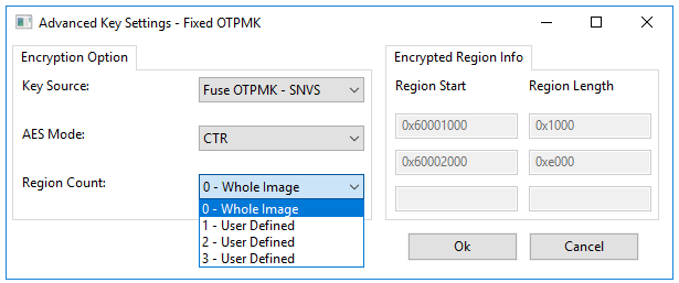
The Step6 operation in the above figure is mainly used to confirm one point: whether BEE_KEY0_SEL is set to From OTPMK[255:128] (bit 13 of Fuse 0x460[31:0], 12 is 2'b10). After Step6 operation, you can see that the Bootable image downloaded into Boot Deivce is all ciphertext from IVT. This example only enables one encryption area. Which areas are encrypted are specified in [Advanced Key Settings], and the maximum support is specified. 3 blocks of encryption.
It is necessary to introduce the following BEE parameter setting page using Fixed Otpmk (SNVS) Key encryption. Set the Region Count and specify the Region range, the default is 0 which means encrypted region is the entire image.
All operations are correct. Set Boot Mode to 2'b10(Internal Boot mode) via SW7 DIP switch on the board, and sets BT_CFG[1] to 1'b1 (Encrypted XIP is enabled). The rest remains all 0s. You can see that the BEE encrypted image is executed normally.
BEE encryption is more secure than HAB encryption, because HAB encryption can only be static decryption after all. When the HAB decryption is completed, all the image plaintext is stored in SRAM/SDRAM. If the hacker illegally accesses SRAM/SDRAM at this moment, it is possible to get all the plain text of the image(But don't worry, You can set JTAG access right for i.MXRT); and BEE encryption can be dynamic decryption, where the CPU will go to decrypt somewhere, there is no complete image plaintext at any time, the hacker can never get all the image plaintext.
The fifth mode is the top security mode, which uses a user-defined Key to perform dual-engine BEE-level encryption on the image. Similar to the fourth mode (single-engine) principle, it is generally used in applications where product security is extremely high. The specific differences between single-engine BEE encryption and dual-engine BEE encryption are as follows:
- The only SNVS Key single-engine BEE encryption uses SNVS Key by default. The SNVS Key is pre-burned and cannot be changed. The user-defined Key dual-engine BEE encryption key is set by the user and needs to be manually burned in Fuse SW_GP2 and GP4 area.
- Unique SNVS Key single-engine BEE encryption only enables BEE engine 0; user-defined Key dual-engine BEE encryption can enable both BEE engine 0 and engine 1. However, it should be noted that no matter how many BEE engines are enabled, the total number of encrypted areas is three.
- The unique SNVS Key single-engine BEE encryption must be used with the HAB signature, because the SNVS Key can only be obtained in the state of HAB Closed; the user-defined Key dual-engine BEE encryption does not have to use the HAB signature.

Select "BEE Encrypted Image Boot" in [Secure Boot Type], click the [Browse] button to select an original image file (must be XIP image in FlexSPI NOR), select "Flexible User Keys" in [Key Storage Region], then click the [Advanced Key Settings] button to configure all BEE encryption parameters, and finally click the [All-In-One Action] button to complete the bootable image generation and download operations.
The Step6 operation in the above figure is mainly used to confirm two points: 1. Whether BEE_KEY0_SEL is set correctly (bits13, 12 of Fuse 0x460[31:0]) and whether BEE_KEY1_SEL is set correctly (bit 15 and 14 of Fuse 0x460[31:0]); Whether the user key is correctly programmed (SW_GP2: Fuse 0x690 - 0x6c0, GP4: Fuse 0x8c0 - 0x8f0).
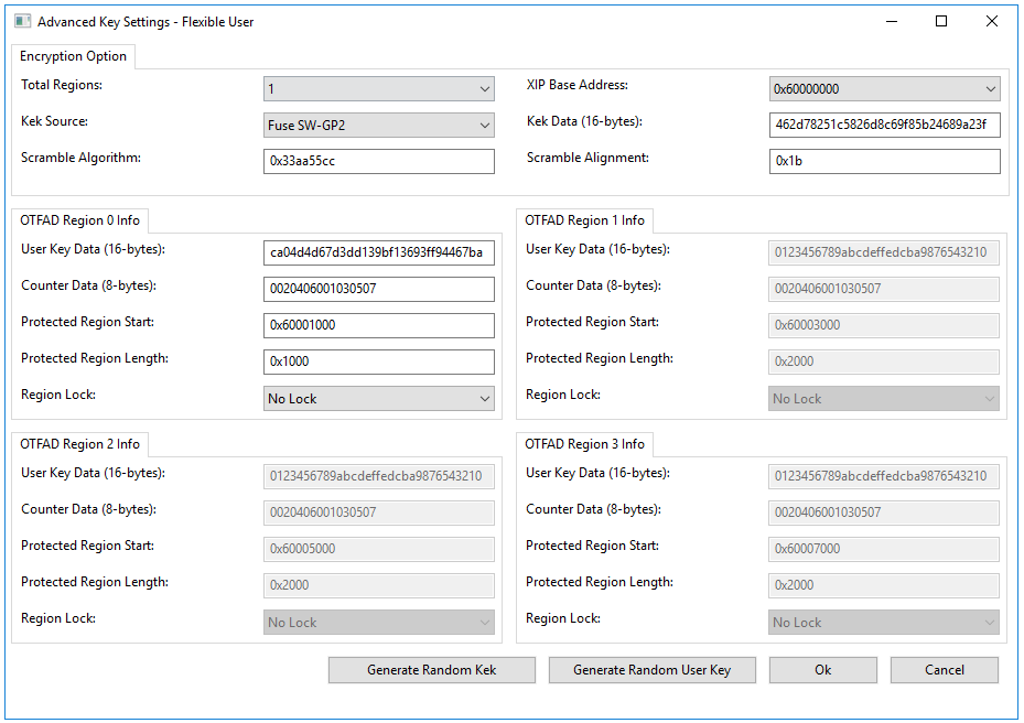
It is necessary to introduce the BEE parameter setting page encrypted by Flexible User Keys as follows. Firstly, select the BEE engine to be activated. You can activate the BEE engine 0 separately, or activate the BEE engine 1 separately. Of course, you can activate the BEE engines(0/1) at the same time. This example activates both BEE engines 0 and 1. After the BEE engine is specified, the storage space of the Key used for encryption is further configured for the engine and the Key (128 bits) is required to manually input. Finally, you need to set the area for encryption protection. In this example, two areas are encrypted, which are 0x60001000 - 0x60001fff (protected by BEE engine 0) and 0x60003000 - 0x60003fff (protected by BEE engine 1).

To confirm that the image is encrypted by the specified area, you can open the unencrypted bootable image file under the \NXP-MCUBootUtility\gen\bootable_image\ folder and compare it with the contents of the image readback window.
All operations are correct. Set Boot Mode to 2'b10(Internal Boot mode) via SW7 DIP switch on the board, and sets BT_CFG[1] to 1'b1 (Encrypted XIP is enabled). The rest remains all 0s. You can see that the BEE encrypted image is executed normally.
NXP-MCUBootUtility burns the user-defined Key into the Fuse SW_GP2/GP4 area for the dual-engine BEE encryption, but the Fuse content of the area can be read back. If the hacker gets the Key, it is still possible to crack Image ciphertext in the external Boot Device. Is there a way to protect the Fuse SW_GP2/GP4 area? Of course, you can lock the specified Fuse area, you can set the Fuse area access rights (read protection, write protection, coverage protection), as detailed in a separate chapter. The NXP-MCUBootUtility tool directly locks the SW_GP2/GP4 area for security reasons.
Compared with single-engine BEE encryption, dual-engine BEE encryption doubles the difficulty from the perspective of cracking. After all, two different keys can be enabled to jointly protect the image from being illegally obtained.
The sixth mode is similar to the fourth mode, FlexSPI on-the-fly encryption module in early i.MXRT chip (eg i.MXRT105x) is BEE, it switches to OTFAD in subsequent i.MXRT chip (eg i.MXRT1011). OTFAD is enhanced than BEE.
The seventh mode is the top security mode. The specific differences between dual-engine BEE encryption and dual-level OTFAD encryption are as follows:
- BEE encryption can support 3 protection regions and 2 user keys; OTFAD can support 4 protection regions, each region can have its own user key, besidesm there is a global key used to protect user keys.
- User keys used for BEE are stored in efuse directly; global key used for OTFAD can be protected by scramble algorithm.
Let's see the OTFAD flexible user key configuration:
kek is the global key, it is stored in eFuse. user keys are saved in OTFAD DEK KeyBlob, and KeyBlob is stored in NOR Flash, kek is used to protect KeyBlob.
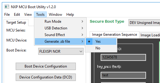
Set Tools/Generate .sb file option as "Yes" in menu bar, then click 【All-In-One Action】 button, A .sb file will be generated into \NXP-MCUBootUtility\gen\sb_image\ folder, this .sb file can be used for MfgTool or RT-Flash tool. Note that clicking 【All-In-One Action】 button will not really perform any boot command on MCU,it just record all boot commands in \NXP-MCUBootUtility\gen\bd_file\imx_application_sb_gen.bd file to generate final .sb file。
Note1: There is one limitation in generating .sb file,you need to reconnect device every time you want ro generate new .sb file,click 【Reset device】 button to move back to initial state,then click 【Connect to ROM】 button.
Note2: If there is necessary efuse operation in generated .sb file, tool will generate three .sb files in total. application_device.sb includes all operations(flash+efuse), application_device_flash.sb includes flash operations only, application_device_efuse.sb includes efuse operations only, it is flexible for production.
Note3: For NOR Flash devices (FlexSPI NOR, LPSPI NOR), you can either connect or disconnect board to generate .sb file.
Note4: [Scan], [Burn] buttons in eFuse Operation Utility window can also be used to generate .sb file which contains efuse operation only.
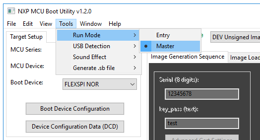
The NXP-MCUBootUtility is set to work in the Entry Mode by default. You can set it to Master Mode through the function menu bar Tools->Option. Some advanced functions are opened in the Master Mode, which is suitable for users who are very familiar with the NXP MCU chip and the Boot ROM.
In the Master Mode, you can uncheck the One Step option, so you can connect to the target device step by step. The main meaning of the single-step connection is that you can connect to the Flashloader to implement the eFuse operation without configuring the Boot Device.

When NXP-MCUBootUtility is in Master Mode, you can see that all eFuse areas are open. You can burn the specified eFuse area at will. The eFuse operation is a bit-by-bit. It can only be written as 1 and when it has been burned to 1 and it cannot be changed. Therefore, the operation of eFuse requires special care.
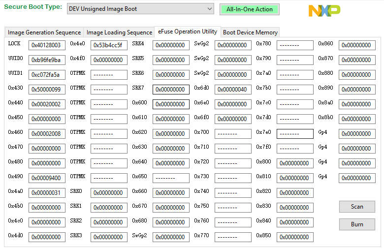
In the previous chapter, the secure boot process, we will burn SRKH (0x580 - 0x5f0), SW_GP2 (0x690 - 0x6c0), GP4 (0x8c0 - 0x8f0), these areas can not be changed once burned, even we want these areas can't only be changed, it can not be read back.
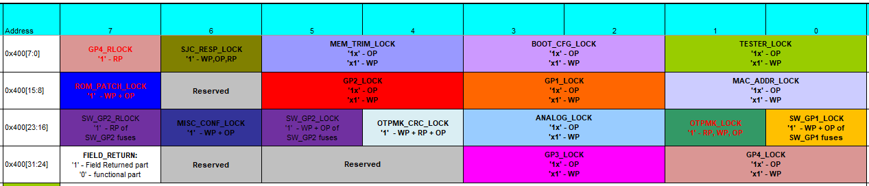
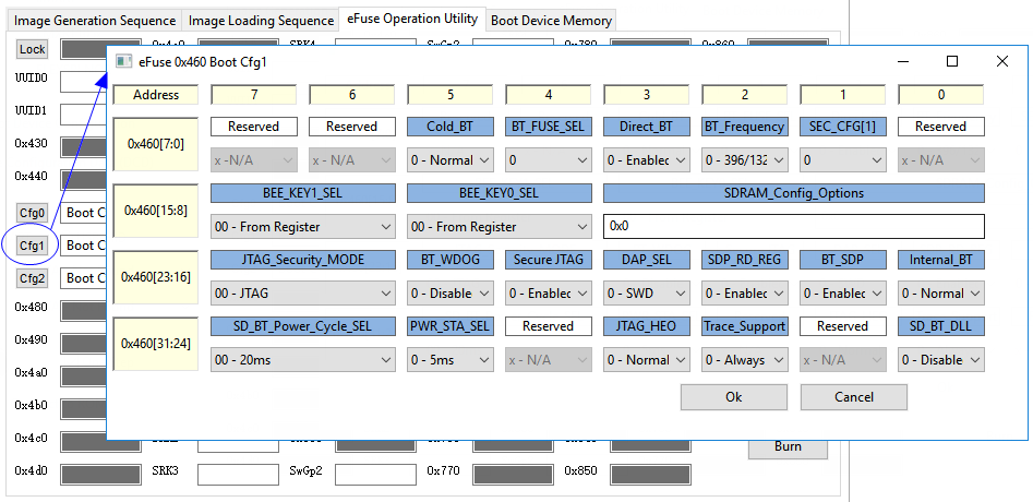
From the above figure, eFuse 0x400 is the Locker of each Fuse function area. We can lock the SW_GP2, and GP4 areas by burning eFuse 0x400. So how do you burn it? In fact, it is very simple, fill in the value you want to burn directly in each eFuse box, click the [Burn] button.
For some mixed eFuse fields, you can also click the index button, then each efuse bits as below:
In the Master Mode, you can click the [Read], [Write], [Execute] button to implement any read, write and execute operations of the FlexRAM, so that the NXP-MCUBootUtility tool can be used as a FlexRAM programmer.

In the Master Mode, you can click the [Read], [Erase], [Write] button to implement any read and write operations of the configured Flash, so that the NXP-MCUBootUtility tool can be used as a general-purpose Flash programmer.

NXP-MCUBootUtility mainly depends on i.MXRT ROM Flashloader and blhost, As Flashloader is often updated with SDK, so we may need to update flashloader for NXP-MCUBootUtility. it is easy to update flashloader, we need to build new flashloader from SDK (middleware/mcu-boot) and rename it to 'flashloader_user.srec' and then put it into /src/targets/MIMXRTxxxx/.