Example: FM Radio Demodulation
First off, this was a learning experience for me. I took a DSP course in university, but just knowing some calculus doesn't help you implement real world DSP systems: it takes practical experience beyond theory. ✊
I wouldn't have gotten nearly as far as quickly as I did without the huge help from Discord users Dutra_CGI(blog) and Darkknight512(blog). Also, I want to extend a big thanks to Deepwave Digital for 1) their help and allowing me use of AIR-T 8201 SDR hardware with the AirStack Sandbox FPGA Development Kit, and also for 2) being a wonderful place to work 🤓.

Files for this demo can be found in examples/sdr.
RF samples flow from the radio front end through the data path and are finally output as audio samples.
- Radio tuned center on FM station
- FIR and decimate down to ~300KSPS needed for FM channel, ~150KHz frequency range.
- Demodulate FM signal, still ~300KSPS, raw FM signal (has mono+stereo+etc)
- FIR and decimate down to 15KHz band for mono audio, output 48KSPS audio.
- FM radio deemphasis, flatten high freq
SDR: AIR-T 8201 hardware and AirStack Sandbox FPGA Development Kit
The specific rates and filtering required for the Deepwave AIR-T SDR platform are as follows:
- IQ from radio: 125MSPS
- 125MSPS decimation by D=500 to 250KSPS
- 3 decimation stages=[5,10,10]
- FM Demodulation using differentiator
- Mono audio decimation
- 250KSPS interpolate by N=24 = 6MSPS
- then decimate by M=125 = 48KSPS
- stages=[5,5,5] # reuses 5x decim
- last decimation stage has low pass filter for 15KHz audio range
- Deemphasis is done like a small one 1 tap FIR filter. Coefficient is region specific.
- SDR platform requires output of 32 bits each cycle
- two 16b samples buffer is not shown in diagrams
- the second SDR channel is used as a debug stream of pre-demodulation 250KSPS data.
- Anti-alias FIR filters were designed with a transition width ~= 1/3 of band
- Except for final decimation stage with 15KHz LPF
- Transition width all falls WITHIN the Nyquist freq
-
http://t-filter.engineerjs.com/
- Helper script to calculate values for
t-filter
- Helper script to calculate values for
def print_fir_config(fs, decim_factors):
  for d in decim_factors:
    bw_in = fs/2
    fs_out = fs/d
    bw_out = fs_out/2
    tw = bw_out/3
    pass_width = bw_out-tw
    stop = bw_out
    print(fs,"Hz decim by",d)
    print("pass",0,"Hz->",pass_width,"Hz","tw",tw)
    print("stop",stop,"Hz->",bw_in,"Hz")
    fs = fs_out

print_fir_config(125e6, [5,10,10])
print_fir_config(6e6, [5,5,5])
print_fir_config(6e6, [24])Building blocks of the design can be found in fm_radio.h. The top level using those components comes together in fm_radio_datapath() in fm_radio.c.
The data path consists of decimation and interpolation FIR filters, FM demodulation, and FM radio deemphasis.
The entire code for the FM radio data path is shown below:
i16_stream_t fm_radio_datapath(ci16_stream_t in_sample){
  // Create separate I and Q streams to work with
  i16_stream_t i_sample = {.data=in_sample.data.real, .valid=in_sample.valid};
  i16_stream_t q_sample = {.data=in_sample.data.imag, .valid=in_sample.valid};

  // First FIR+decimate to reduce frontend radio sample rate down to ~300KSPS
  //  Stage 0
  i_sample = decim_5x(i_sample);
  q_sample = decim_5x(q_sample);
  //  Stage 1
  i_sample = decim_10x(i_sample);
  q_sample = decim_10x(q_sample);
  //  Stage 2 (same decim func as stage 1)
  i_sample = decim_10x(i_sample);
  q_sample = decim_10x(q_sample);

  // Connect debug output to be after decim, before demod
  debug_data = uint16_uint16(q_sample.data, i_sample.data); // Concat
  debug_data_valid = q_sample.valid & i_sample.valid;

  // FM demodulation
  ci16_stream_t fm_demod_in = {
    .data = {.real=i_sample.data, .imag=q_sample.data},
    .valid = i_sample.valid & q_sample.valid
  };
  i16_stream_t out_sample = fm_demodulate(fm_demod_in);

  // Down sample to audio sample rate with fixed ratio
  // (N times interpolation/M times decimation) resampler
  //  Interpolation:
  out_sample = interp_24x(out_sample);
  //  Decimation:
  //    Stage 0:
  out_sample = decim_5x(out_sample);
  //    Stage 1:
  out_sample = decim_5x(out_sample);
  //    Stage 2: Last decimation stage is configured with extra audio low pass 15Khz
  out_sample = decim_5x_audio(out_sample);

  // FM deemphasis of audio samples
  out_sample = deemphasis_wfm_pipeline(out_sample);
  return out_sample;
}In addition to the core fm_radio_datapath(), fm_radio.c also includes a small wrapper sdr_wrapper() function to expose specifically structured and named ports for the top level generated HDL.
Building the design can be done like so:
./src/pipelinec examples/sdr/fm_radio.c --top fm_radio --out_dir ../pipelinec_output
The PipelineC tool outputs a read_vhdl.tcl script that can be sourced into the AirStack Sandbox Vivado project. The top level interface of the design when instantiated with the Deepwave Digital AXIS infrastructure looks like so:
// Always ready for input samples from radio
assign dwd_rx0_m_axis_tready = ~dwd_rx_axis_rst[0];
assign dwd_rx1_m_axis_tready = ~dwd_rx_axis_rst[1];
fm_radio fm_radio_inst(
    .clk_125p0(dwd_axis_clk),
    // Input IQ
    .i_data_val_input(dwd_rx0_m_axis_tdata[15:0]),
    .q_data_val_input(dwd_rx0_m_axis_tdata[31:16]),
    .iq_valid_val_input(dwd_rx0_m_axis_tvalid),
    // Output audio samples
    .audio_samples_data_return_output(dwd_rx0_s_axis_tdata),
    .audio_samples_valid_return_output(dwd_rx0_s_axis_tvalid),
    // Output debug data
    .debug_data_return_output(dwd_rx1_s_axis_tdata),
    .debug_data_valid_return_output(dwd_rx1_s_axis_tvalid)
);
// Always outputting two audio samples
assign dwd_rx0_s_axis_tkeep = '1;
assign dwd_rx0_s_axis_tlast = 0;
// Debug output full word too
assign dwd_rx1_s_axis_tkeep = '1;
assign dwd_rx1_s_axis_tlast = 0;fm_radio.h uses dsp/fir_decim.h, dsp/fir_interp.h, and the base dsp/fir.h header to declare various FIR filter configurations.
These header files are used with 'arguments' as if invoking a macro. For example, declaring a FIR filter function called my_fir looks like:
#define fir_name my_fir
#define FIR_N_TAPS 4
#define FIR_LOG2_N_TAPS 2 // log2(FIR_N_TAPS)
#define fir_data_t uint16_t
#define fir_coeff_t uint8_t
#define fir_out_t uint26_t // data_width + coeff_width + log2(taps#)
#define FIR_COEFFS {1, 2, 3, 4}
#include "dsp/fir.h"
See examples/fir.c for more syntax.
dsp/fir_decim.h is a header that is included as if invoking a macro. The decimation by N design includes a shifting window of samples, every N cycles the low pass FIR filter function is applied to the window and a single sample is output.
dsp/fir_interp.h is a header that is included as if invoking a macro. The interpolation by N design first inserts N-1 zeros into the data stream (increasing sample rate). Then this stream of pulses surrounded by zeros is filtered using a low pass FIR to smoothly interpolate an output signal. The FIR includes output gain adjustment to normalize the signal since interpolation introduced gain of 1/N.
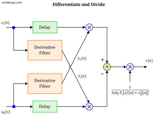

The fm_demodulate() function defined in fm_radio.h implements demodulation via differentiation and
could be written like so:
i16_stream_t fm_demodulate(ci16_stream_t iq_sample){
  static ci16_t iq_history[3];
  static ci16_t iq_dot;
  static int16_t output;
  if(iq_sample.valid){
    // save input
    iq_history[0].real = iq_sample.data.real;
    iq_history[0].imag = iq_sample.data.imag;
    // Calculate derivative
    iq_dot.real = iq_history[0].real - iq_history[2].real;
    iq_dot.imag = iq_history[0].imag - iq_history[2].imag;
    // Calculate output (I[1] * Q') - (Q[1] * I') w/ fixed point correction
    output = (iq_history[1].real * iq_dot.imag) >> 15;
    output -= (iq_history[1].imag * iq_dot.real) >> 15;
    // update history & return
    iq_history[1] = iq_history[0];
    iq_history[2] = iq_history[1];
  }
  // Output scaling factor
  float df = FM_DEV_HZ/SAMPLE_RATE_HZ;
  float scale_factor_f = 1.0 / (2.0 * 3.14 * df); // 1/(2 pi df)
  float f_i16_max = (float)(((int16_t)1<<15)-1);
  int32_t scale_factor_qN_15 = (int32_t)(scale_factor_f * f_i16_max);
  int16_t scaled_output_q1_15 = (output * scale_factor_qN_15) >> 15;
  i16_stream_t output_stream = {
    .data = scaled_output_q1_15,
    .valid = iq_sample.valid
  };
  return output_stream;
}
Note that in the final design, the demodulation function was modified to not include the output scaling factor, and to isolate the static registers into a separate window function for autopipelining.
Deemphasis is implemented with a region specific coefficient:
// Deemphasis
// 75e-6 Tau (USA)
// 50e-6 Tau (EU)
#define USA
#if defined(USA)
#define fm_alpha (int16_t)(7123)
#else
#define fm_alpha (int16_t)(9637)
#endif // TAU
i16_stream_t deemphasis_wfm(i16_stream_t input){
  /*
      Sample rate: 48000Hz
      typical time constant (tau) values:
      WFM transmission in USA: 75 us -> tau = 75e-6
      WFM transmission in EU:  50 us -> tau = 50e-6
      More info at: http://www.cliftonlaboratories.com/fm_receivers_and_de-emphasis.htm
      Simulate in octave: tau=75e-6; dt=1/48000; alpha = dt/(tau+dt); freqz([alpha],[1 -(1-alpha)])
  */
  static int16_t last_output = 0;
  int16_t output = 0;
  if(input.valid){
    // process
    output = (fm_alpha*input.data) >> 15;
    output += ((32767-fm_alpha)*last_output) >> 15;

    // save last & return
    last_output = output;
  }
  i16_stream_t output_stream = {.data = output, .valid = input.valid};
  return output_stream;
}Individual components have been simulated: decimation, interpolation, and demodulation.
The files in the test bench tb/ directory have been setup for testing a single component at a time, ex: the demodulation function alone.
tb.c consists of a single MAIN function wrapping the module to be tested. The test bench is configured with a set of input samples from a header file:
  #include "samples.h"
...
  static in_data_t i_samples[I_SAMPLES_SIZE] = I_SAMPLES;
  static in_data_t q_samples[Q_SAMPLES_SIZE] = Q_SAMPLES;
  static uint1_t samples_valid[SAMPLES_VALID_SIZE] = SAMPLES_VALID;
And the function under test returns output samples that are printed to screen:
  // Print valid output samples
  if(i_output.valid & q_output.valid){
    printf("Cycle,%d,Sample IQ =,"out_data_format","out_data_format"\n", cycle_counter, i_output.data, q_output.data);
}compare_samples.py generates input samples into "samples.h" and compares output by parsing the sim_output.log samples printed to screen during simulation.
From in tb/ directory, the following is an example command line that will: clear previous output, generate input samples, run simulation using those samples, save log of output samples, and finally parse+display+compare the expected vs. simulation output waveforms.
rm sim_output.log; python3 compare_samples.py && ../../../src/pipelinec tb.c --sim --comb --cocotb --ghdl --run 123 &> sim_output.log && python3 compare_samples.pyThe hardware test script airt_test.py is based on the Deepwave provided tutorial for reading samples from the AIR-T device. It otherwise includes minor changes to be compatible with the AirStack Sandbox FPGA Development Kit build in use. For example: the int16_t audio samples are pulled from SOAPY_SDR_CS16 complex IQ data returned by sdr.readStream() - instead of interleaved IQ, its just 2 audio samples per complex sample returned.
python3 ./airt_test.py
The script can be configured with a number of seconds to record, ex. audio_seconds = 5. And the output file fm_radio_audio.wav can be played with a media player.
Running at 125MHz there should easily be ~500-2000x resource savings possible from the many decimation stages that reduce the sample rate well below the clock rate. Excited to try a go at saving resources? Reach out for more information - always happy to help!
TODO CIC filters, combining/multiplexing multiple decim FIRs (ex. I and Q)...
How to deal with flow control needed for more complicated interpolation? Ex. if back-to-back interpolation is needed then stalling/flow control pushing back into data path is required. Currently data path is free flowing with valid flag - but no ready flag to push back flow control exists.