This project contains Arduino device code, Processing game code and Python server code implementing a game controller that uses inertial navigation to detect orbit around a rotational axis outside of the controller's body. This data is then used as a controller input to a flappy bird clone.
Submitted for Department of Engineering thesis "Building a Physical Analogue for Feedback Rich Systems" at Australian National University. The completed thesis is attached to this repository.
- http://www.dsfcode.com/using-processing-via-the-command-line/
- http://eli.thegreenplace.net/2009/08/12/framing-in-serial-communications
- https://github.com/firmata/protocol
- https://docs.python.org/3/howto/sockets.html
- https://en.wikipedia.org/wiki/Asynchronous_I/O#Polling
- http://tldp.org/HOWTO/TCP-Keepalive-HOWTO/overview.html
- https://en.wikipedia.org/wiki/Keepalive
- https://docs.python.org/3/library/_thread.html#module-_thread & http://www.dabeaz.com/python/UnderstandingGIL.pdf - that Python threads are actually pthreads limited by the GIL, which means context switches occur with
timer.sleep(0), IO operations, and a timer interrupt specified by the Python runtime. - For the event loop to work with have to deal with the possibility of partial reads and partial writes. In most cases, we should only care about partial reads, we'll make sure the write goes through before continuing (so we will have blocking writes). This is because writes are meant to be real time, so bad writes can just be dropped. But partial reads means we have to maintain a buffer, and the buffer pair algorithm is needed to in case we have read overflow, that is read more than enough for 1 message (this is to improve performance rather than to read 1 byte a time).
- Relationship between rolling window increment and rolling window size actually gives rise to both latency and accuracy and efficiency tradeoff.
- http://obogason.com/fundamental-frequency-estimation-and-machine-learning/
- http://tkf.github.io/2010/10/03/estimate-frequency-using-numpy.html
- https://gist.github.com/endolith/255291
- http://exnumerus.blogspot.com.au/2010/04/how-to-fit-sine-wave-example-in-python.html
- http://scipy-cookbook.readthedocs.io/items/FittingData.html
Polling vs Busy Waiting:
The difference between the two is what the application does between polls.
If a program polls a device say every second, and does something else in the mean time if no data is available (including possibly just sleeping, leaving the CPU available for others), it's polling. If the program continuously polls the device (or resource or whatever) without doing anything in between checks, it's called a busy-wait.
This isn't directly related to synchronization. A program that blocks on a condition variable (that should signal when a device or resource is available) is neither polling nor busy-waiting. That's more like event-driven/interrupt-driven I/O. (But for example a thread that loops around a try_lock is a form of polling, and possibly busy-waiting if the loop is tight.) http://stackoverflow.com/a/10594529/582917
Sine wave characteristics:
l = lambda
v = phase velocity
f = frequency
T = period

     v
l = ---
     f

     v
f = ---
     l

     1
f = ---
     T

     l
v = ---
     T
A phase offset is an instantaneous position on a single waveform cycle. A 0 degree or 360 degree phase offset is equivalent to the starting point of a wave. 180 degrees is in the middle of the wave. 90 degrees is the crest and 270 degrees is trough of the wave.
Phase velocity = Wavelength divided by Period. Period is the time it takes to go from 1 crest to another crest, so basically start to a finish of a wave cycle. Frequency is the number of cycles per second.
When the wavelength and period is the same, then the phase velocity is 1. Wavelength is measured in meters, while period is measured in seconds.
Wavelength is given by the distance between two successive peaks/troughs in a displacement vs. position graph. Period is given by the distance between two successive peaks in a displacement vs. time graph.
In an accelerometer graph representing orbital motion, assuming 40 Revolutions per Minute = 2/3 Revolutions per Second, would mean that 1 revolution takes 1.5 seconds. This should show up as 0.6666... Hz on the graph and 1500 milliseconds as the period. The wavelength doesn't matter because we don't actually care about the distance travelled in our orbit controller, only the direction and frequency.
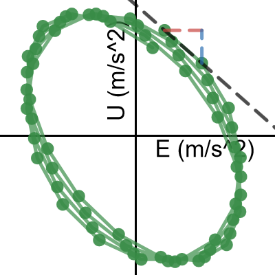
The data is:
2.8697358266694493, 10.153302161258436
6.460969159839447, 6.9903282338783743
9.0304916052962074, 2.6756155308647633
10.17839883866681, -2.1005916224136736
9.7260377925625967, -6.5742215226332306
7.7438110971825962, -10.029607133544683
4.5402200574177174, -11.913974615019903
0.6138514486397435, -11.925873082486047
-3.4242193954793008, -10.063399083682736
-6.945532507391289, -6.6245011026244169
-9.4020528452473773, -2.1593153778824958
-10.411463022501062, 2.6178419076657491
-9.8166647831462441, 6.9427470536936493
-7.710228786944179, 10.123525203104277
-4.4199874937304147, 11.651332727361739
-0.45801337974073675, 11.28175926905354
3.5590768042977032, 9.0739271846290865
7.0060883889102223, 5.3810334706297853
9.3465501549839978, 0.79384722473040692
10.216207342675848, -3.9537983888284671
9.4797119729492003, -8.1024007868643704
7.2516875563932324, -10.988289069235661
3.8788898104229705, -12.149794488179921
-0.11376022127295496, -11.401105709432661
-4.1048715809279983, -8.8619939012201083
-7.4732927800225823, -4.9386523926766221
-9.6947839131178366, -0.25871606917244694
-10.423606061975299, 4.4291442509233274
-9.5463299278775207, 8.3749901112657117
-7.1994892547951954, 10.94758650239859
-3.748331575569114, 11.735383413308186
0.27002661858099841, 10.612353368997487
4.2301933130557616, 7.7581526220746717
7.5158330525412218, 3.6293807203281379
9.6155895177045974, -1.1134638112923769
10.202669808941147, -5.7116464406409646
9.1857044394286813, -9.4295748617208428
6.7229675078132738, -11.672475060265134
3.1977439122238325, -12.081540033124751
-0.84132270238858831, -10.591329785644493
-4.7656173930128665, -7.4402400669121853
-7.9643875975658416, -3.1323651114207935
-9.939796825169525, 1.6431446212044598
-10.384404798770509, 6.1223289972115298
-9.2290155276478583, 9.5886324054563126
-6.653446536522142, 11.487534435835212
-3.0585431961332685, 11.515259045510792
0.9962063310136845, 9.6673710018687764
4.8797463119656141, 6.2394854069648282
7.9876669915144571, 1.7799767975899237
9.8362711278805879, -2.9977468374907192
10.137853591460548, -7.3293711964237973
8.845477983020773, -10.521946518892491
6.1602815198844656, -12.064741928630792
2.5001713035439228, -11.710949387634868
-1.5652161151366459, -9.517166706834729
-5.4031693886240948, -5.8343433354154559
-8.4163735903550467, -1.2516373722899143
-10.135872555878583, 3.4978347496269047
-10.294054272976654, 7.6542782522569279
-8.866300333346933, 10.552767858094485
-6.0748173869486362, 11.729618928026229
-2.3540542955345503, 10.996565213813398
Acquiring acceleration delta between T1 and T2.
c\ =\ \left(-\frac{\left(U\left[T_2\right]-U\left[T_1\right]\right)}{\left(E\left[T_2\right]-E\left[T_1\right]\right)}\right)E\left[T_1\right]+U\left[T_1\right]
y=\left(\frac{\left(U\left[T_2\right]-U\left[T_1\right]\right)}{\left(E\left[T_2\right]-E\left[T_1\right]\right)}\right)x+c
Note whether East acceleration is Positive/Negative and Increasing/Decreasing.
y=U\left[T_1\right]\left\{\left\{E\left[T_1\right]\ge E\left[T_2\right]:\ E\left[T_1\right],E\left[T_2\right]\right\}\ge x\ge \left\{E\left[T_1\right]\ge E\left[T_2\right]:E\left[T_2\right],E\left[T_1\right]\right\}\right\}
Note whether Up acceleration is Positive/Negative and Increasing/Decreasing.
x=E\left[T_2\right]\left\{\left\{U\left[T_1\right]\ge U\left[T_2\right]:\ U\left[T_1\right],U\left[T_2\right]\right\}\ge y\ge \left\{U\left[T_1\right]\ge U\left[T_2\right]:U\left[T_2\right],U\left[T_1\right]\right\}\right\}
Consider the resultant change in acceleration (delta) between T1 and T2.
The opposite direction of the resultant change in acceleration is the actual rotational tangent direction.
The combination of the rotational tangent direction and the displacement position at the circle is what tells us whether we are rotating clockwise or anticlockwise.
- Service discovery between the game client and server (OS-specific)
- Autobuilding the processing application via command line
- Custom IDing of the USB controller
- Udev script to autostart game upon plugging the controller (using mdns for service discovery, and python-avahi for the game code)
- Packaging up the game to be deployable
- Detailing controller manufacturing
- In the future, the server should be resilient to device plugins and unplugs. Detect both of these and continue running. When unplugging, it should signal game to reset (or close the game), and then restart from the beginning. It should also deal with when the device stops answering, and attempt to reset the game controller until it works, or after a few retries, indicate that the device is broken, and signal the game to exit, and close itself. The server itself should be starting the game, so the game should be a child process of the parent process.