The scope of this project is use of neural networks in order to estimate depth on fish-eye images to enhance the perception capabilities of an autonomous boat.
Last week I had a problem with my computer, it basically died after five years of usage (not that bad actually) it was kind of a horrible experience as deadlines are approaching and there is a lot of things to be done before that.
Luckily at the beginning of this project I started using Docker so setting up my environment has not been painful at all. I'm going to explain how to set everything to work.
Follow the installation process in here: https://docs.docker.com/install/linux/docker-ce/ubuntu/
Follow the installation process: https://docs.docker.com/compose/install/
git clone git@github.com:RoboticsURJC-students/2017-tfm-mikel-diez.git

or

git clone https://github.com/RoboticsURJC-students/2017-tfm-mikel-diez.git
Inside the External folder clone the viz repository (there might be already a viz folder, remove it)
cd 2017-tfm-mikel-diez/code/Externals
rm -rf viz
git clone git@github.com:JdeRobot/viz.git
By default 3DWebViz listens to the port 11000 but I'm using the 12000 (this is done because I used cameraserver and they where in conflict). The file under Externals/viz/3DVizWeb/public/config.yml should look like the following:
Server: "localhost"
Port: "12000"
updatePoints: 10000 #miliseconds
updateSegments: 1000 #miliseconds
linewidth: 2 #width of the line
pointsize: 8 #size of the point
camera: #camera position
  x: 50
  y: 20
  z: 100
This will launch the container. Both out applications use the XServer so first we will need to allow docker to access it.
xhost +local:docker
sudo docker-compose up
There are two different things to launch the Vision application and the 3DViz. Open two different tabs.
Vision application:
sudo docker exec -it 2017-tfm-mikel-diez_jderobot_1 /bin/bash
python Vision/vision.py
3DVizWeb:
sudo docker exec -it 2017-tfm-mikel-diez_jderobot_1 /bin/bash
cd Externals/viz/3DVizWeb
npm install
npm start
Now everything should be ready.
Some advances in the h264 viewer, now we can change between cameras without breaking them and also I've created a multi-camera viewer. Some more work in the styling is to be done but is some work to be done in the next iteration.

I've made some analysis in how used are the cpu and the memory. The results are as follows.


| FPS | CPU | Memory | Network |
|---|---|---|---|
| 25 | 50% - 20% | 8% | 400KB/s |
| 12 | 20% - 10% | 5% | 200KB/s |
So I maid a major breakthrough in the H264 field and now I have a streaming from the cameras in the UAV directly to the browser. There is much to be done but this first step is already here.

I also started making it so you can change between cameras:
As a matter of fact we saw that the data traffic was of between 60 and 80 KB which is around 8 times smaller than with motion jpeg for a bigger image with more FPS.
Puron viewer with h.264 from video file streamed with node websocket.

Video of recontruction without projection restriction

Video with epipolar restriction

I've been taking a look at https://github.com/131/h264-live-player which has several examples on h.264 video play in the browser. The main examples I'm interested in are:
- streaming using raspivid from the node code
- streaming using tcp from raspivid
As far as my investigation in this matter goes, it seams that node.js is a pretty solid option to take into account, as it seams to promise latencies of around 150ms.
The idea of all the solutions around this that I've found are based in having a websocket to stream de video.
Working on this I've been having a lot of problems to be able to get que 3D ray of a pixel, this theoretically easy process is being impossible to achieve. After trying unsuccesfuly to do it on my own I've tried using the progeo.py function to help me backproject the pixel:
def backproject2(point2d, K, R, T):
    RT = np.hstack((R, T))
    RT = np.vstack((RT, [0, 0, 0, 1]))
    iK = np.linalg.inv(K)
    Pi = np.array([point2d[0], point2d[1], 1.0], dtype=np.double).reshape(3, 1)
    a = np.dot(iK, Pi)
    aH = np.array([a[0], a[1], a[2], 1], dtype=np.double)
    RT2 = RT.copy()
    RT2[0, 3] = 0
    RT2[1, 3] = 0
    RT2[2, 3] = 0
    RT2[3, 3] = 1
    b = np.dot(np.transpose(RT2), aH)
    translate = np.identity(4, dtype=np.double)
    translate[0, 3] = RT[0, 3] / RT[3, 3]
    translate[1, 3] = RT[1, 3] / RT[3, 3]
    translate[2, 3] = RT[2, 3] / RT[3, 3]
    b = np.dot(translate, b)
    outPoint = np.array([b[0] / b[3], b[1] / b[3], b[2] / b[3], 1])
    return outPoint
Not only my cameras are wrongly displayed but the lines don't cross each other:

Having the following matrices and with a "correct" opencv reconstruction I should be able to have this right.
R = [[ 0.99898286  0.00558905 -0.04474376]
 [-0.00356533  0.99897241  0.04518197]
 [ 0.04495031 -0.04497648  0.99797624]]

T = [[90.62655468]
 [ 3.51641911]
 [10.22665275]]

K_a (matrix of camera a)= [[1.43958854e+03 0.00000000e+00 6.58021160e+02]
 [0.00000000e+00 1.44238025e+03 2.76884781e+02]
 [0.00000000e+00 0.00000000e+00 1.00000000e+00]]

K_b (matrix of camera b)= [[1.43850152e+03 0.00000000e+00 6.23111868e+02]
 [0.00000000e+00 1.44075734e+03 3.44642276e+02]
 [0.00000000e+00 0.00000000e+00 1.00000000e+00]]
This is the script I'm using: https://github.com/RoboticsLabURJC/2017-tfm-mikel-diez/blob/ae79751925625b3394b641975758f79614e9f3a3/code/apps/TestCommands/TestEpipolar.py
As part of the need of the project I'm also creating a reduced version of the software in order to be able to put it in the raspberry pi. There are certain things that won't be needed there (jderobot, 3dviz....) so everything should be useful in that version.

In order to create a more real reconstruction I check back that the opoint in image a is also in the epipolar of the point in b (and viceversa)
Correct match
Wrong match
It goes from 255 to 0 where 255 is the closest and 0 the oposite.
I saw that the algorithm is so orientation invariant that some matches are 180º rotated which should never happen, if I change this I get the following distance image. The main difference is the image is that the left line I had that seemed closer than it really was.
- Check raspberry pi and h264 video streaming
- Better file for distance image
- Use a d-max restriction
- Fish-eye
I took some videos but they all have some kind of reed filter over them (I'll try to improve that) Video Streaming with VLC

Video Streaming using an MJPEG software to web

Video Streaming using a sofware and a h264 video

Unfortunately I'm using a USB camera without native h264 support, hence no video in h264 can be extracted from there and I cannot do further test unless I use the native camera module for raspberry.
One of the things to do was to create a file where not only the distance points were ther but also the unknown ones.
(x, y, depth)
134 122 0.0
135 122 0.0
136 122 0.0
137 122 0.0
138 122 31.333560841383093
139 122 0.0
140 122 0.0
141 122 0.0
142 122 0.0
This is in milimeters so the floating coma could and mybe should be truncated.
With this we can create this images for example. The first one is a image with circles on different intensities (darker the closer)

This one is the points with distances but the viewer can't interpret it correctly.

- Depth Image to file
- Check rasbperry pi and h264 video streaming
- Use a bigger baseline
- Use a d-max restriction
- Fish-eye
I've created a class and a file that creates and reads a list of points with their depths:
# points (x, y, depth)
794.0 66.0 25.7565359078
835.0 67.0 107.103449649
840.0 67.0 75.9568031612
845.0 67.0 56.2796129371
850.0 67.0 19.6973447612
817.0 68.0 395.814651194
863.0 68.0 23.155889435
868.0 68.0 20.5708455968
788.0 69.0 16.1893999973
799.0 69.0 13.2290620964
804.0 69.0 13.3564450507
I didn't have time to test the streaming (at least right now) because I had some problem with the sd card or my raspberry (it was corrupted) but I have it now installed and ready,

With a new baseline of around 170mm we are ready for some new reconstructions

For outdoors the points are very far from camera and I can see them, I'm still searching for a way to make the scale smaller.
New video with outdoor reconstructions

I had some problems with my computer (yes my new computer) and managed to fix them. Then did some test: A different scenario:

I also tested how the algorithm behaved with HSV but did not work correctly, I'm still testing this to see what went wrong.

Unfortunately couldn't test in outdor images as the problems with the computer prevented me to do so.
I tried to take some fotos outside but my cameras seem to handle badly when there is a lot of light. I'll try again.

In my test for a feature detector I found the FREAK detector which is the fastest (5 to 7 seconds) and more precise:

Also created an image with the "distance" the dark color means that is close and bright read for "far" objects

- Refine different descriptors usage and reconstruction
- Quantitative analysis of the degrees change toleration
- Fish-eye introduction
Extra Points:
- Faster sampling algorithm
It was outside the scope of this weeks but I managed to make the algorithm 1.8s faster by optimizing the function that samples the points of the image A.
Old algorithm

New algorithm

The points are not exactly the same but they are quite similar and from 1.95 seconds we got down to 0.15s. That's quite an improve.
It seems that I've domesticated the feature detector of opencv at least with ORB. I get way more points and unfortunatelly way more missmatches. I'm working in a threshold.
Canonical

Euler Angles = (-3.3713558063735305, -3.13934643228478, -5.5404691855671775)

Euler Angles = (-3.173178259185197, 2.151335716097801, 18.784725635994242)

I added a threshold and it seems that the first two stand correctly (way better than the version with the color matching) but 18º seem to be to much for this descriptor.
Canonical

Euler Angles = (-3.3713558063735305, -3.13934643228478, -5.5404691855671775)

Euler Angles = (-3.173178259185197, 2.151335716097801, 18.784725635994242)

I did some test with other descriptors
Canonical (SURF)

Canonical (BRISK)

(BRISK) Euler Angles = (-3.173178259185197, 2.151335716097801, 18.784725635994242) !!!WORKS!!!

FLANN based Matcher is regarded as faster than brute force for "large data-sets" It might apply here.
Image of the features in an epiline

Image of the matching of one point (wrong)

Image of the matching of one point (correct)

Video of wrong reconstruction (cameras right)

We had the theory that the calibration was off in some aspects and that it was leading to wrong epilines in our system. To test this hypothesis I tested several of the different calibrations I had previously make to check if it wass the case.


This images show how our hypothesis was wrong, calibration seems to be just right and the epilines prove it so the problem has to be in a different place.
I've observed that there is a problem when representing the cameras, the left side seems to be a bit smaller than the right one.
Having the following camera matrix:
[[473.84607711   0.         428.59054565]
 [  0.         473.84607711 302.68935657]
 [  0.           0.           1.        ]]
The resolution is 1280x720 so it seems odd that the principal point is that displaced to the left that much but I don't really now if that's normal.
Nevermind I think I found a problem:
[[7.68018389e+02 0.00000000e+00 1.11667735e+03]
 [0.00000000e+00 7.68018389e+02 2.76146118e+02]
 [0.00000000e+00 0.00000000e+00 1.00000000e+00]]

[[928.22191407   0.         304.207201  ]
 [  0.         928.22191407 313.74538326]
 [  0.           0.           1.        ]]
But it seems that the problem increases when the cameras are in non canonical positions. For example when they are "canonical" (they never are really canonical) the camera matrix is like the following ones:
[[928.22191407   0.         304.207201  ]
 [  0.         928.22191407 313.74538326]
 [  0.           0.           1.        ]]

[[970.66091468   0.         480.58301926]
 [  0.         970.66091468 312.04958344]
 [  0.           0.           1.        ]]
They are similar but not the same.
Right now my guess with what is broken is the following:
- When I match patches, if they are rotated they won't match, hence the problem when cameras are not canonical.
- I think the problem with calibration is that I only use images that are visible in both images. This is necessary for stereo calibration but for the single camera I could use more images and cover both full images. This might be the reason for the poor results.
Finally I managed to draw correctly the images.

Canonical position

Roll to the left

Roll to the right

Pitch Down

Pitch Up

Yaw to the center

- Improve calibration robustness
I saw that the images I was taking where in the wrong size and that made them to be of worst quality so I've change to opencv images from video and the result is quite better.

Anyway the cameras position seems wrong. I'm taking a look at that right now.

- Improve calibration robustness
| Image A | Image B |
|---|---|
 |
 |
euler_angles = [0.018462264472724192, -0.004943072062613791, 0.02942619084545588]
translation_vector = [9.49622799e+01, -4.87026222e-15, -0.00000000e+00]
| Image A | Image B |
|---|---|
 |
 |
euler_angles = [0.022930599394765803, 0.006603138159345876, -0.6403221824270738]
translation_vector = [8.74872087e+001, -1.60908569e-014, 4.29837112e-322]
| Image A | Image B |
|---|---|
 |
 |
euler_angles = [0.08092445737732676, -0.07023280153640832, -0.009926486033918892]
translation_vector = [ 9.09670595e+0, 5.46578292e-15, -0.00000000e+00]

- Test angles with cameras
- Draw cameras with the angles

euler_angles = [0.002667008916093765, 0.02449494160296928, -0.08205145388299641]

euler_angles = [0.017367707615372836, 0.026282819353049974, 0.5364164674416368]

euler_angles = [-0.01249720507311161, 0.11237875935343324, -0.43610179440262115]
- Improve efficiency of matcher
- Test angles with cameras
So this has been a big failure of a week to be honest. I've invested large amounts of hours investigating different ways to make the algorithm more efficient and faster.
Las week we had the algorithm running at 15s per image this time it's working at 9s per image at a resolution of 960x540. It's not enough. My next step has been to try lower resolutions (480x270) and I get a speed of 3s but I need to fix some parameters and the reconstruction is jet to be completed.
I've also tried by taking less points of interest from image A and of course get way better results in time (2s per image) but the reconstruction is way less dense.
See the video to view an example (keep in mind that I changed some staff in the reconstruction but din't have time to fix a problem with the plane position. It's a known bug and will fix it soon.)

Also I've incremented the threshold for the points to be considered correct and the results are now way better.
Didn't have time for this part.
- Improve calibration to get real measures
- Optimize matching
- Small Optimization
- Bellow 1 second
In previous weeks we had a calibration that returned a reconstruction in an unknown scale. One of the objectives of this week was to correct it in order to get real measures directly.
In order to do this I had to measure the pattern squares (28mm) and added it to the calibration. Now I have real distances.
For representation I apply a factor of 0.1 so the 3DViz creates a better representation.
I'm still working on this, last week we had a speed of 25 seconds per frame and now is down to 15 seconds. It's not enough so I'm still working on this.
####### Less use of cv2.matchTemplate One of the steps that used most of the time was the use of matchTemplate function from OpenCV (13 seconds) so I had to reduce its usage. To do this, instead of using 3 patches for the same column (we use a epiline range of +-1) y match a column and select the better point. This reduces the use a lot and has gotten it to around 5 seconds. It's still to much but it shows me the way to go.
####### More efficient interest points structure (Work in progress) I wish I had this finished but I've been unable to do so. The idea is the following:
# Get all the non-zero (border) pixels of image B
non_zero_pixels = np.array(cv2.findNonZero(border_image), dtype=np.float32)

# Create a structure on size m (height of the image) and in each element a list of size n (the number of non-zero pixels in that row) with the value of the column where the pixel is.
for non_zero_pixel in non_zero_pixels:
    non_zero_pixels_structure[non_zero_pixel[0][1]].append(non_zero_pixel[0][0])

# Example
[
    [24, 43, 65, 67],
    [31, 12, 123],
    ...
    [1]
]
####### Even less use of cv2.matchTempalte Once I get the previous point finished y plan to use this function only once for every epiline, reducing the amount of calls drastically.
This will mean that each call lasts more but it will be way faster.
Edit (03/05/2019) : I've been thinking that rectifying the images could be a great solution for eficiency.
- Obtain the kRT matrices from the calibration instead of the current stereo matrix. (For each camera)
- Add 3D cameras to the 3DwebViz using the calibration matrices
- Log times on the console in order to detect where most of the time is used on the application
- Change some parameters in order to improve speed
- Measure the FPS of the video processing (once is faster)
- Check some profiling tools and investigate them
As I've been using the OpenCV functions from the beginning I've been neglecting the obtention of the kRT matrices here is the result: ####### Camera 2
k = [[  2.37832668e+03   0.00000000e+00   7.00384617e+02]
 [  0.00000000e+00   2.37832668e+03   3.40740051e+02]
 [  0.00000000e+00   0.00000000e+00   1.00000000e+00]]
R = [[ 1.  0.  0.]
 [ 0.  1.  0.]
 [ 0.  0.  1.]]
T = [[ 0.]
 [ 0.]
 [ 0.]
 [ 1.]]
####### Camera 2
k = [[  2.37832668e+03   0.00000000e+00   7.00384617e+02]
 [  0.00000000e+00   2.37832668e+03   3.40740051e+02]
 [  0.00000000e+00   0.00000000e+00   1.00000000e+00]]
R = [[ 1.  0.  0.]
 [ 0.  1.  0.]
 [ 0.  0.  1.]]
T = [[ -9.53577170e-01]
 [ -7.80413327e-18]
 [  0.00000000e+00]
 [  3.01148768e-01]]
Both cameras are the same so it makes a lot of sense that the intrinsic parameters are equal and both cameras seem to be correctly aligned. The only difference (as expected) is the translation vector. The first camera is on the origin and the second its displaced in the "x" axis (and barely in an other axis but is to small to consider)
I added some logs to the reconstruction (as the calibration can be done offline the times are not critical) and obtained the following:
INFO:root:[11:07:57.391277] Load Images
INFO:root:[11:07:57.472219] Start Match Points
INFO:root:[11:07:58.902518] Start Match Points With Template
INFO:root:[11:09:43.375470] End Match Points With Template
INFO:root:[11:09:43.375613] Start Undistort Points
INFO:root:[11:09:43.376371] End Undistort Points
INFO:root:[11:09:43.376445] Start Triangulate Points
INFO:root:[11:09:43.382578] End Triangulate Points
INFO:root:[11:09:43.382760] Convert Poinst from homogeneus coordiantes to cartesian
INFO:root:[11:09:43.453446] End Convert Poinst from homogeneus coordiantes to cartesian
INFO:root:[11:09:43.453621] Return cartesian reconstructed points
INFO:root:[11:09:43.453776] End Match Points
INFO:root:[11:09:43.453892] Setting Points and Segments
INFO:root:[11:09:43.454969] Run vision server
INFO:root:Total time: 0:01:46.063928
This is the result for a single file (images) reconstruction and it takes it around 1 minute 46 seconds which is not acceptable. But the responsible for this is clear, is the matching function and is where the efforts should be.
As talked I've tried reducing the epipolar range I'm using (+-4 pixels) to a new one (+-1 pixel) and it gives the following output:
INFO:root:[11:35:50.056661] Load Images
INFO:root:[11:35:50.141154] Start Match Points
INFO:root:[11:35:51.502285] Start Match Points With Template
INFO:root:[11:36:32.935945] End Match Points With Template
INFO:root:[11:36:32.936088] Start Undistort Points
INFO:root:[11:36:32.936828] End Undistort Points
INFO:root:[11:36:32.936902] Start Triangulate Points
INFO:root:[11:36:32.942012] End Triangulate Points
INFO:root:[11:36:32.942088] Convert Poinst from homogeneus coordiantes to cartesian
INFO:root:[11:36:32.977115] End Convert Poinst from homogeneus coordiantes to cartesian
INFO:root:[11:36:32.977329] Return cartesian reconstructed points
INFO:root:[11:36:32.977482] End Match Points
INFO:root:[11:36:32.977554] Setting Points and Segments
INFO:root:[11:36:32.978514] Run vision server
INFO:root:Total time: 0:00:42.922084
We earn a minute by doing this and actually the result is pretty much the same.
After this I tried reducing the image to 640x480 pixels but had some problems with the calibration. Anyway I managed to reduce it a 25% (960x540) and got the following times:
INFO:root:[12:53:22.193265] Load Images
INFO:root:[12:53:22.280576] Start Match Points
INFO:root:[12:53:23.130515] Start Match Points With Template
INFO:root:[12:53:48.033126] End Match Points With Template
INFO:root:[12:53:48.033289] Start Undistort Points
INFO:root:[12:53:48.033951] End Undistort Points
INFO:root:[12:53:48.034053] Start Triangulate Points
INFO:root:[12:53:48.038218] End Triangulate Points
INFO:root:[12:53:48.038304] Convert Poinst from homogeneus coordiantes to cartesian
INFO:root:[12:53:48.069251] End Convert Poinst from homogeneus coordiantes to cartesian
INFO:root:[12:53:48.069460] Return cartesian reconstructed points
INFO:root:[12:53:48.069602] End Match Points
INFO:root:[12:53:48.069718] Setting Points and Segments
Connect: default -h localhost -p 9957:ws -h localhost -p 12000
INFO:root:[12:53:48.070760] Run vision server
INFO:root:Total time: 0:00:25.877815
It's a big improvement but not even close to the speed we need.
The bottleneck seems to be in the following code, the code takes around 0.012 seconds per point to analyze which is too much.
def __match_points_hsv_template(self, points, lines, image1, image2, image2_borders):
    height, width, depth = image2.shape
    points_left = None
    points_right = None
    lines_right = None
    patch_size = 20
    image1 = cv2.cvtColor(image1, cv2.COLOR_BGR2HSV)
    image2 = cv2.cvtColor(image2, cv2.COLOR_BGR2HSV)
    for line, point in zip(lines, points):
        left_patch = self.__get_image_patch_gray(image1, point[0][1], point[0][0], int(patch_size / 2))
        best_mean_square_error = 0.9
        best_point = None
        for column in range(patch_size, width - patch_size):
            row = int((-(column * line[0]) - line[2]) / line[1])
            for epiline_offset in range(-1, 1):
                if (row) < image2_borders.shape[1] and (row) > 0:
                    if image2_borders[row][column + epiline_offset] == 255:
                        right_patch = self.__get_image_patch_gray(image2, row, column, int(patch_size / 2))
                        if right_patch.shape == (patch_size, patch_size, 3):
                            similarity = cv2.matchTemplate(right_patch, left_patch, cv2.TM_CCORR_NORMED)
                            similarity = similarity[0][0]
                            if similarity > 0.9 and similarity > best_mean_square_error:
                                best_mean_square_error = similarity
                                best_point = np.array([[column + epiline_offset, row]], dtype=np.float32)
        if best_point is not None:
            if points_left is None:
                points_left = np.array([point])
                points_right = np.array([best_point])
                lines_right = np.array([line])
            else:
                points_left = np.append(points_left, [point], axis=0)
                points_right = np.append(points_right, [best_point], axis=0)
                lines_right = np.append(lines_right, [line], axis=0)


    return points_left, points_right, lines_right
Lets show a video of the new cameras and coordinates direction. Now the camera coordinates are converted to our world coordinates system.

I've been doing some research with profiling tools (cProfile for python) and for the bottleneck and got the following:
   ncalls  tottime  percall  cumtime  percall filename:lineno(function)
     5727    0.006    0.000    0.044    0.000 function_base.py:4523(append)
        1   14.209   14.209   25.265   25.265 imagematcher.py:297(__match_points_hsv_template)
   198520    0.299    0.000    0.299    0.000 imagematcher.py:334(__get_image_patch_gray)
     5727    0.005    0.000    0.006    0.000 numeric.py:484(asanyarray)
        2    0.007    0.004    0.007    0.004 {cvtColor}
   196417   10.203    0.000   10.203    0.000 {matchTemplate}
        1    0.000    0.000    0.000    0.000 {method 'disable' of '_lsprof.Profiler' objects}
    14159    0.032    0.000    0.032    0.000 {numpy.core.multiarray.array}
     5727    0.032    0.000    0.032    0.000 {numpy.core.multiarray.concatenate}
  1936863    0.471    0.000    0.471    0.000 {range}
        1    0.001    0.001    0.001    0.001 {zip}
It seems that 14s correspond to the function itself (with its multiple loops) and the rest to the matchTemplate function from openCV which we call nearly 200.000 times. I need to see if I can do this more efficient.
- Fix problem with triangulation
- Print pixel piramid and plane grid using segments (not objects)
As you know I've been having some problems with the triangulation from images, if I select the points manually seemed to work ok but in this case I finally managed to get a kind-off accurated reconstruction: (see video)

- A better triangulation finished:
- In 3dWebViz draw the cameras (as pyramids) and a plane at the depth the selves should be.
- Improve application input/output pipeline
- Modify to take video files
- 3DViz comunnication live
- OpenCV for videos Use
- Fish-eye
- Calibrate fisheye cameras once and for all
There have been some problems in this part. I have no problem drawing segments and points, but objects is a different matter. I've managed to do this with points and will be trying to create de objects. (See video)

I've been doing some research about this and it seems that there is a function that helps a lot at taking videos, both from cameras directly or file:
video = cv2.VideoCapture(0) # To read from camera

video = cv2.VideoCapture('my_video.mpg') # To read from a video file
Then with the following method the program can just take frame by frame:
video = cv2.VideoCapture(0)
video.read() # Gives the next frame
Then the code is pretty similar as the old one, take the frame and calculate the same things.
I got nice results with this after a few attempts. Reconstruction is not great but this video is not about that (I'll address that problem later)

Here a video of the capture, seems that the cameras don't get a great resolution I might need to change some parameters somewhere to fix this:

I managed to add to my 3D reconstruction a direct connection with 3DWebViz (live connection) here is a very simple video of this with a point moving. (See video)

- Improve matching with different measures
- Improve and understand better the triangulatepoints function
- Full fish-eye camera calibration
I've been using custom metrics to get the similarity between patches, but now I'v tried the OpenCv function cv2.matchTemplate.
I've used only the three methods that are normalized in order to be able to create a threshold. Bellow I show the results:
BGR with TM_CCORR_NORMED

BGR with TM_CCOEFF_NORMED

BGR with TM_SQDIFF_NORMED

Even if they still have problems with the yellow books it seems that is a bit better than the MSE I used in previous weeks.
I still don't know exactly how this works on the inside, but also tried to use this same matchers with hsv images. Te results aren't bad but they are not explendid either.
HSV with TM_CCORR_NORMED

HSV with TM_CCOEFF_NORMED

HSV with TM_SQDIFF_NORMED

In order to recreate the 3D scene I'm trying to use the OpenCV function cv2.triangulatePoints which in python has the following definition:
points4D = cv2.triangulatePoints(projMatr1, projMatr2, projPoints1, projPoints2[, points4D])The points are the ones that the matching algorithm gives me back and the projection matrix are obtained with the use of cv2.stereoRectify
r1, r2, p1, p2, q, roi1, roi2 = cv2.stereoRectify(
			self.calibration_data["cameraMatrix1"],
			self.calibration_data["distCoeffs1"],
			self.calibration_data["cameraMatrix2"],
			self.calibration_data["distCoeffs2"],
			(1280, 720),
			self.calibration_data["R"],
			self.calibration_data["T"],
			alpha=rectify_scale
)
Something seems to be out of place and I'm still investigating it.
I've been reading that cv2.triangulatePoints takes as points undistorted points, so I'm checking that out.
So finally I've managed to get what seems to be a better reconstruction, there are still points in a wrong position BUT they are yellow and yellow points seem to be matching in a wrong way. (See video):

- Points matching in an RGB color space
- Full fish-eye camera calibration
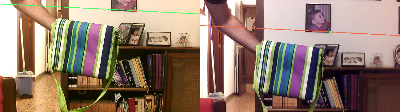
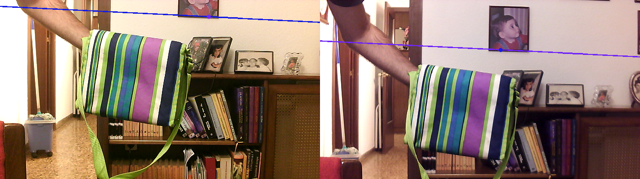
As agreed I started working in a tool to see how the points in both images are matched. Unsurprisingly all the lines follow the same direction as they are all following the epiline and they all go in the same direction.
Matching with gray images and MSE threshold of 80

Matching with gray images and MSE threshold of 50

Matching with rgb images and MSE threshold of 50

Matching with rgb images and MSE threshold of 50 with an epiline range of +-4 pixels.

Matching with hsv color space taking all the channels and without considering the circularity of H

Matching with hsv color space taking only H and S with threshold of 50

Matching with hsv color space taking only H and S with threshold of 25

As can be seen in the mos of the miss-matches happen in the lower line of yellow books. I might need to try go get a more texturized images where de difference between interest points is higher.
Result of a reconstruction (video):

With this matches:

As can be seen it seems that the yellow points tend to be wrongly matched, hence the reconstruction fails. The rest of the points seem to have a more interesting position but still seems to be wrong.
What am I doing right now?
- First find the pixel in both images (similar pixel color tend to make it fail)
- Use the function
cv2.triangulatePointsto calculate the 3D points - Convert the points returned by the function from quaternions to cartesian coordinates (x/w, y/w, z/w)
- Save the reconstruction with the color
- Show this using 3DWebViz
More about epilines, now with more points

With even more points

More dense reconstruction (click the image to see the video):

So in the end I managed to paint some pretty neat epilines

And could make my first reconstruction... which is a bit disappointing as all the points are in the same plane but the position seems odd.

Finally I managed to create a docker environment to work here I show how it looks (click the image to see the video):

The main features of this are the following:
- I have created a docker image with the jderobot installation and other things I might need using a base of ubuntu 16.04
- I use a docker-compose.yml file to launch the image and set the ports/devices(cameras)/display
- From inside the docker the usb plugged cameras can be accessed
- From inside the docker the application GUI is generated
This is now in a very early stage but seems to be working correctly. I also managed to use GUI with docker on OSX but the cameras access seem to be far more complicated. Once the documentation is ready I'll post it here again with the links.
After a few fixes now I can also run de 3DVizWeb inside docker without problem. See the video bellow.

Now lets do a 3D reconstruction.
I make some major changes in my calibration process to avoid certain mistakes I was having:

I also started doing some experiments with docker as I some times find my self with a different computer than my own and now I managed to create a working environment that I can move to different machines.
Anyway I'm still working in the 3D reconstruction but now things should go more smoothly.
So after a few more attempts I managed to use the 3DVizWeb to create a "mash" of points and some segments.


In the end it was easier than it seemed and I had to do the following under the viewerBuffer.py file: Points:
bufferpoints = [
    jderobot.RGBPoint(),
    jderobot.RGBPoint(10.0,0.0,0.0),
    jderobot.RGBPoint(-10.0,0.0,0.0),
    jderobot.RGBPoint(0.0,10.0,0.0),
    jderobot.RGBPoint(0.0,-10.0,0.0),
    jderobot.RGBPoint(0.0,0.0,10.0),
    jderobot.RGBPoint(0.0,0.0,-10.0)
]
Segments:
bufferline = [
    jderobot.RGBSegment(jderobot.Segment(jderobot.Point(10.0,0.0,0.0),jderobot.Point(-10.0,0.0,0.0)), jderobot.Color(0.0,0.0,0.0)),
    jderobot.RGBSegment(jderobot.Segment(jderobot.Point(0.0,10.0,0.0),jderobot.Point(0.0,-10.0,0.0)), jderobot.Color(0.0,0.0,0.0)),
    jderobot.RGBSegment(jderobot.Segment(jderobot.Point(0.0,0.0,10.0),jderobot.Point(0.0,0.0,-10.0)), jderobot.Color(0.0,0.0,0.0))
]Finally by using double sided tape I managed to transform my pinhole webcams to a fish-eye webcam. In the images bellow you can see how the angle of the fish-eyed camera is wider than the normal pinhole camera. Also the quality of the image as it reaches the edges decreases.


I'm having some trouble calibrating this images due the bad quality of the images. I might need to try a different lighting and a different pattern for the calibration (a bigger one).

Last year I started with this really interesting project and now I'll start again working on it. I might change a bit how this entry looks en the next days or even switch to Github but we'll see. First lets make a summary of where did I leave everything:
- Build stereo camera system: Done
- Stereo calibration for pinhole cameras: Done
- Stereo calibration for fish-eye cameras: ToDo
- Use of 3DVizWeb to represent the dots: ToDo
- Stereo pixels match (using simple patch comparison): Done
Lot of things to do, yes. The first step in this project is to have a classic 3D reconstruction and after that have a classic 3D reconstruction with fish-eye cameras. Anyway once the calibration of the fish-eye cameras and the rectification is done both problems should be similar to solve.

One of the most critical things for me to progress in this project as the 3D reconstruction works is to see if I can show this in a 3D viewer this is the first successful attempt to use it. I'm still researching this but it seems to be changing coordinates every few seconds. I'll take a look.
Then for fish-eye calibration I run into this tutorial and will be trying to use it to help me achieve my goals.
I finally managed to create a stereo calibration. As said in previous logs I used the example of the OpenCV documentation to calibrate the single cameras, but then I needed to have the stereo pair and its relative calibration.
Again OpenCV really helps with the process and has a function stereoCalibrate that pretty much do the job for you, you only need to pass the correct parameters to it and now everything is ready to rectify the images.

I've been like for a month without working much on the thesis (I really regret it), but now I'm back on business. I'm going to write here on the go as the new updates happen instead of waiting until the end to write everything. This way I'll be more engaged with all this (thesis and wiki and github).
Well, first update. I finally got David Pascual's digitclasifier to work! Yes after several problems I got it to work with the new JdeRobot packages.

With this new JdeRobot packages the only problem I encounter was that I didn't have the h5py package installed (is listed at [https://keras.io/#installation|Keras] installation documentation as an optional package) but then everything went smoothly.
So, this thesis is going to be about depth estimation in stereo images using Deep Learning (likely using convolutional neural networks) but at least in a first attempt CNN will be used to match the corresponding pixels in both images.
Lets divide the 3D reconstruction from stereo images of a scene in different steps(some of the could contain other sub-steps, but from now we'll go with this):
- Images acquisition
- Pixel matching
- Distance estimation *3D image reconstruction
The step that will be using CNN is the second. To do this, first a classic geometric solution for stereoscopic 3D reconstruction will be implemented to create a non-dense image of the scene. In the following subsections I'll explain how this first solution is going to be implemented.
By using the JdeRobot cameraserver I'll connect two cameras to a computer that will process the images. But in a very early stage I'll test the algorithm with a still image (just a photograph) so I'll be able to take it without worrying about other connectivity to test the solution. The rest will come in a later stage when real-time video processing will be necessary.
An other critical part in the acquisition hardware is its calibration, we need to know its intrinsic and extrinsic parameters. The intrinsic parameters are specific to a camera, and once calculated they won't (likely) change, on the other hand, extrinsic parameters are the ones telling the camera position in the real world (rotation, position, tilt).
For this task (calibration) I'll be using OpenCV calibration function (here a tutorial) and I'll need some kind of chess-board pattern. The one in the image is a home-made one.

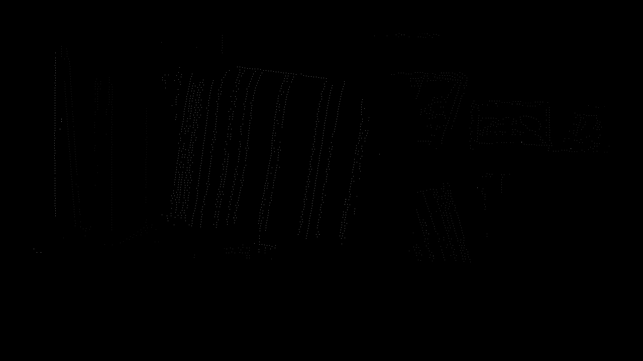
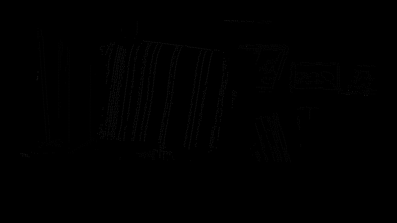
In the future this stage will include the CNN but for now I'll proceed with a more classic approach. The objective (at first) is to create a sparse reconstruction, so I'll take only border/corner pixels. Why is that? Well, pixels with high gradient (corners,borders,rough textures) contain much more information than plain surfaces.
For this I'll apply a sobel filter to both images to get the high gradient. Then I'll start taking points in the left image and trying to find them in the right one. But I'll use some restrictions: *Not all the pixels will be taken only the strongest in the neighbourhood *I'll use the epipolar restriction, so will only search for coincidences in a bunch or lines over on bellow the original one. *The pixel on the right image will always be more to the right than in the left image, so there is no use on searching it in the first pixels. *I'll take the most similar patch except if the similarity is to low or there are several high similarity patches.
And for the similarity measure I'm thinking in a minimum mean square error as it's a basic similarity operator.
Once the pixels have been matched is when the distance estimation begins. By knowing the calibration parameters and the pixels of interest this becomes a geometry problem.
With two points (pixel and camera origin) we can get a line and with two lines we can find an intersection (or the point where they are the closest) and that's the point we are looking for. That's our reconstructed 3D point. I'll extend this in future updates, as this is something I'm going to implement for sure.
Once a list of 3D points is found it's time to show them on the screen. We might use them in many ways but for now lets stick to the previous parts as they are still the main parts of this.
I was having some problem with my python packages version so I decided that it was better to start with a fresh Ubuntu 16.04 installation. I found that ROS had updated some packages and the dependencies where broken so I tried to install it from source code following the [Installation#From_source_code_at_GitHub|installation instructions] from this official source. I didn't have much luck doing this.
There are other staff I had to do for this Mondays meeting:
- Read the thesis of two former students of the course.
- Marcos Pieras
- David Pascual
- Read one paper:
They propose a new approach that speeds up the time of a Neural Network to process distances from a minute to less than a second (GPU time). They use a siamese architecture as is standard for this challenges and treat the problema as a multiclass classification. The classes are all the posible disparities.
The problem of distance detection has always been high due its enormus amount of applications in the industry for automation, being the cameras the cheapest sensor compared to others such as LIDAR. This approaches for stereo camera find an interest patch in the left image and find the probability of a patch in the right image to be the same one. In this paper they try to do this matching by using CNN (convolutional neural networks).
Other approaches further process with more layers after at the exit of the siamese network but they just compute a simple cost-function to compute the iner product on the representation of both images to know the matching score.
Training: For the left image they take random patches for which the ground-truth is known. They size of those patches is the same as the size of the network receptive field. For the right size however they take a bigger patch. Having a 64-dimensional output for the left size and a |yi|x64 dimensional one for the right one. (if I'm not wrong |yi| is all the possible disparities.
Testing: For testing the network computes the 64 dimensional feature for every pixel in the image (only once to maintain efficiency)
For this first week I had two task that could be differentiated:
- Test some of the examples the JdeRobot framework.
- Installation: No problema at all with the installation of the framework, I did it with the .deb packages and as I use Ubuntu 16.04 everything went as planned.
- Cameraserver: Here I found a major hardware problem, my desktop doesn't have a camera so is kind of difficult to use this examples without it. I'll try to get one for the next week so I can try this.
- Turtlebot + KobukiViewer: I'm still struggling with this example. Y get the following error /usr/include/IceUtil/Handle.h:46: IceUtil::NullHandleException in the next days I'll try to solve it.
- ArDrone + UAVViewer: Works perfectly out-of-the-box, I've been flying the drone over the scenario, it's a bit tricky but everything worked correctly.
- Read the thesis of two former students of the course.