Verifying hardware operation
Once you have the hardware assembled and connected to the PC it is time to check that it functions correctly. You should work through the following and ensure that you can communicate with each piece of hardware. Make a note of which classes you need to use and any communication details, such as COM port numbers.
BakingTray communicates with the laser in order to stop acquisition should it drop out of modelock. Available laser control classes are in the components/laser directory. Let us say you have a Chameleon laser and it is connected to your motherboard serial port, COM1. The following sample session confirms we can connect to the laser and demonstrates some features of the laser control class.
>> c=chameleon('COM1');

Setting up Chameleon laser communication on serial port COM1
Connected to Chameleon laser on serial port COM1

>> [~,status]=c.isReady
status =
    'Laser not powered on'
% So let's turn on the laser with the key switch...

% Test if laser shutter is open (0 means it's closed, 1 means it's open)
>> c.isShutterOpen
ans =
     0
>> c.openShutter; % Let's open the shutter
>> c.isShutterOpen
ans =
     1
% Yep, shutter is now open

% Let's read and then change the wavelength
>> c.readWavelength
ans =
   920

>> c.setWavelength(940);
>> c.readWavelength
Failed to read wavelength from Chameleon. Likely laser is tuning.
ans =
   NaN

% Wait 5 seconds...
>> c.readWavelength
ans =
   940
% Nice

% Close communications with the laser
>> delete(c)
Disconnecting from Chameleon laser
Closing serial communications with Chameleon laser
Most vibratomes consist of a DC motor that turns a cam which produces lateral motion of an assembly that in turns holds the blade. You will now ensure you can set the vibratome to run at a desired speed and also stop the vibratome. Attache the blade holder to the vibratome as you would for normal operation. You should try a range of speeds and choose the fastest speed that doesn't cause nasty resonances (you'll hear them). The following sample session demonstrates this with the Faulhaber MCDC motor controller, with which we interface via a serial connection.
>> f=FaulhaberMCDC('COM2');
Setting up Faulhaber MCDC3006 DC motor controller.
Motor max speed: 60 revs per second.

%Let's start a gentle vibration
>> f.startVibrate(7); % You should now see a modest vibration of the blade
>> f.stopVibrate;  % And we stop it

% Try a range of speeds and stop once it becomes more noisy
>> f.startVibrate(10); % quiet
>> f.startVibrate(11); % quiet
>> f.startVibrate(12); % still quiet
>> f.startVibrate(13); % Getting loud
>> f.startVibrate(12); % <--- This is the setting we'll use
>> f.stopVibrate;

% Terminate the session
>> delete(f)
Closing connection to Faulhaber MCDC motor controller
Don't run the vibratome too fast. Choose a slower speed that produces good results. If you run it too fast you will wear away the axel or the bearings and may need to replace the whole unit after a year or two.
BakingTray can also run devices such as the Leica VT1200 (the unit used by Economo et al) by gating its operation with a TTL pulse via the JaneliaLeicaContoller class.
The X/Y/Z sample translation stage is pushed up and down by what we will refer to as a Z-jack, to distinguish it from any stage that might be driving the objective. You will now ensure that you can connect to the motor controller and issue motion commands. Most devices, such as those sold by Aerotech, PI, or ThorLabs, will allow you to issue motion commands in mm. A few motor controllers (such as that on the TissueCyte 1000) are calibrated stepper motor drivers that require you to measure how many motor pulses there are per mm. Since this is the more complicated scenario, this is what will be demonstrated here.
Before proceeding with this step ensure the area surrounding the stage is clear of obstructions.
Remove the objective, the water bath, and the blade holder.
The motion control classes page describes how BakingTray handles motion control hardware.
Briefly, each physical motion axis consists of a linear stage and a controller for that stage.
BakingTray represents these as separate software entities: a class that inherits linearstage represents the stage and a class that inherits linearcontroller represents the stage controller.
To connect to the TC1000 Z-jack from the command line we first need to build the stage class then attach it to the controller:
% Make an instance of the Haydon 43k4U linear stage class
>> tStage=haydon43K4U
tStage =
  haydon43K4U with properties:

          positionUnits: 'mm'
                 axisID: ''
         invertDistance: 1
         positionOffset: 0
    controllerUnitsInMM: 1
               axisName: []
                 minPos: []
                 maxPos: []
% That creates an instance of the class. This instance needs to be
% populated with reasonable settings:
>> tStage.minPos=0;
>> tStage.maxPos=40;
>> tStage.axisName='zAxis';
>> tStage.controllerUnitsInMM=1.5305E-4; % We'll show how to derive this later
Now it's time to make an instance of the controller.
% The controller class for this Z-jack is an AMS_SIN11. Let's make an instance of
% that and attach it to the stage we just made:
>> A = AMS_SIN11(tStage);

% The following command will connect to the device and then immediately start
% a downward reference motion until it reaches the lower limit switch. This will
% be considered the zero position. Locations upward from this are positive.
% YOUR SYSTEM MUST HAVE FUNCTIONAL LIMIT SWITCHES FOR THE REFERENCING MOVE TO WORK
>> A.connect('COM8');
Device returned:
 K= 5/ 3,I= 2001/ 1,V= 10014/ 1,E= 100,,1/10thn=A
Homing axis on AMS_SIN11..

% Indeed it considers itself to be at 0 mm
>> A.axisPosition
ans =
     0

>> A.absoluteMove(10); %move up 10 mm
>> A.axisPosition
ans =
   10.0000

% Do not disconnect yet from the device.
The stepper motor controller instructs the motor how many steps to take, it doesn't know anything about the number of mm the actuator has travelled. The conversion factor of mm to steps was defined above as:
tStage.controllerUnitsInMM=1.5305E-4;
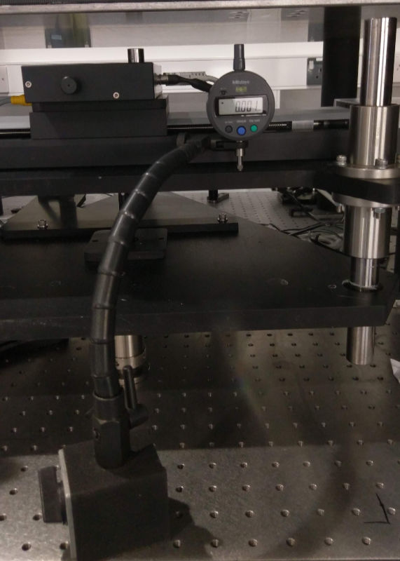
This value is correct for our hardware but you should derive it again here. For this you will need a Mitoyo measuring gauge sold by ThorLabs and an arm of some sort to clamp it to. You can clamp to the thicker portion with a 9.5 mm diameter right below the main body (see the ThorLabs CAD PDF from the link above). The arm holding the gauge can be strong, so take care not to damage the gauge by driving the stage into it.
>> A.absoluteMove(15);
>> A.absoluteMove(10); % We will move down next. This gets rid of backlash
>> A.attachedStage.controllerUnitsInMM=1; % scaling factor is now one to one
>> A.attachedStage.maxPos=1E6; % Otherwise the controller will refuse to move the axis
Now set to the measuring gauge and make a note of the reading. Move the stage down by 10,000 steps:
A.relativeMove(-10000);
Take a note of the reading again. The calibration value is the difference between those readings divided by 10,000. In our case:
>> (3.218-1.687)/10000
ans =
   1.5310e-04
That's very close to the value of 1.5305E-4 which we had measured previously. Enter your value as shown below and return the max pos to a safe value
>> A.attachedStage.controllerUnitsInMM=1.310E-4; %Your value here
>> A.attachedStage.maxPos=40;
>> A.absoluteMove(10); % Get everything back as before
Your Z-jack should now be calibrated.
Confirm that the stage moves as expected by taking a few 1 mm steps and reading the value of the gauge:
>> A.relativeMove(-1);
>> A.relativeMove(-1);
>> A.relativeMove(-1);
>> A.relativeMove(-1);
>> A.relativeMove(-1);
Ignore a value obtained right after a change of direction. To confirm that the referencing is repeatable you should move to an absolute position (10 mm in the following example), place the gauge at that point and take a reading, then reference the stage and move back there.
>> A.absoluteMove(10); % Note reading on gauge
>> A.referenceStage;
Homing axis on AMS_SIN11.................
>> A.absoluteMove(10); % Note the reading again
Repeat the above two or three times. The readings at the start and end should match pretty closely. If the readings are about 100 microns out, that is likely OK.
The X/Y sample stages translate the sample during a tile scan and drive the sample into the blade during cutting. Detailed instructions for setting up the PI stages.
The PIFOC will be controlled by ScanImage but now is a good time to get to know it and ensure it's behaving well. Mount the objective you will be using into the PIFOC and start ScanImage. Run the actuator tuning and set up reasonable parameters for, say, 5 depths spaced 10 μm apart. Save these in the settings file as normal.