Home
The X-ray irradiation machine of the SiLab consists of several sub-systems. The high voltage electronics and control panel are mounted in the lower half of the machine. The cabinet volume for irradiation purposes is accessible via two large doors equipped with lead-glass windows.
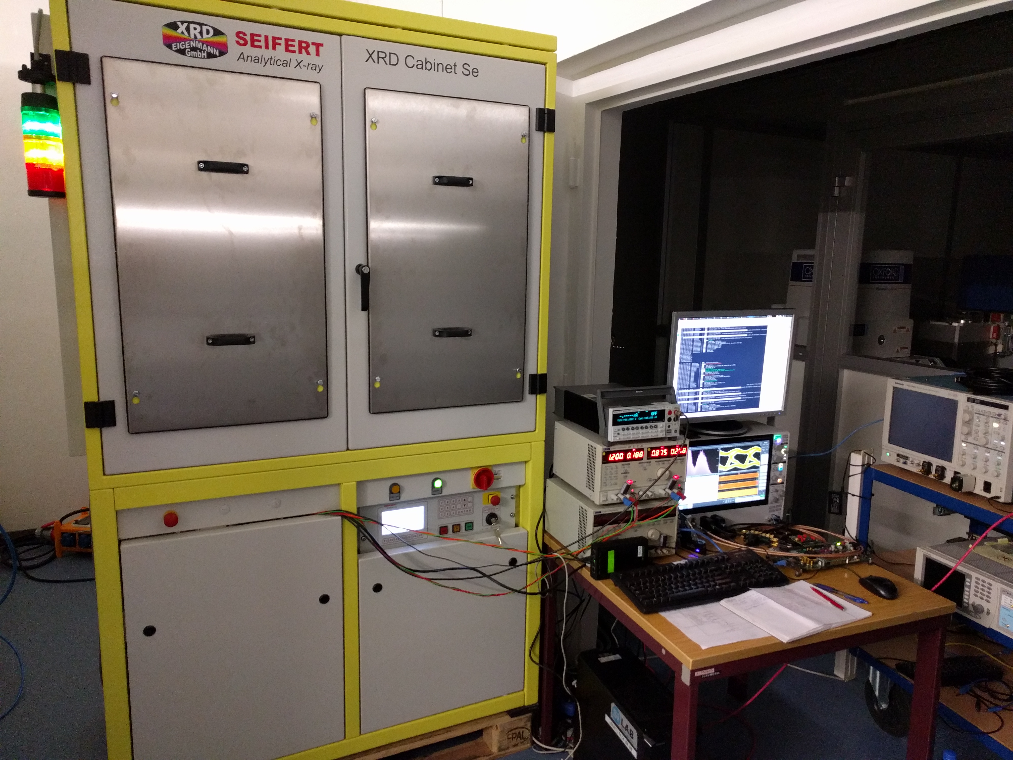
Figure 2: Machine overview
The cabinet is sealed against radiation leakage and can be operated with closed or open steel window covers. They can be removed by lifting and then pulling them towards you. Inside the cabinet a large solid aluminium base plate with M6 mounting holes can be used to fix and align equipment like motor stages. Cables can be fed through the cable tunnel on the left side, far away from the tube high voltage cables which are routed through a dedicated cable tunnel on the right side of the base plate.

Figure 2: Cabinet
The X-ray tube is fixed in a central position at the top of the cabinet (distance to the base plate: ?cm). It is intentionally tilted by 6° to compensate the angled beam (see figure 2).
Two red laser pointers with line optics are mounted close to the tube and provide an almost parallax-free alignment cross in the beam center (+-1mm). Both lasers have been carefully adjusted in terms of translation and rotation to allow for precise DUT alignment independent of the distance to the X-ray tube.
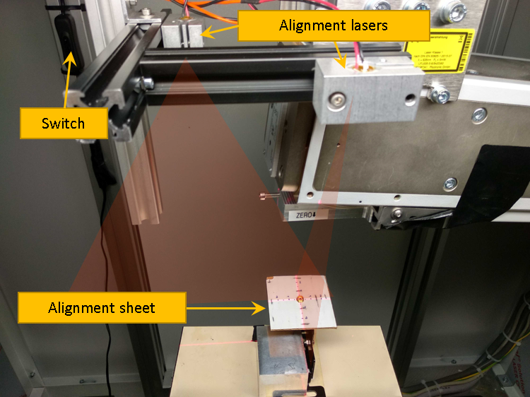
Figure 3: Alignment lasers
Another useful tool for beam alignment is a special X-ray fluorescence paper, which glows green in the presence of X-ray photons. As an example, it can therefore be used for visual cross-checks of the beam shape itself or its alignment in respect to the laser. Several sheets are available and they can be cut into shape if needed. The backside is sticky if the protection foil is peeled off.
A collimator support has been mounted on the primary beam output side of the tube assembly. It holds filter inserts into place and defines the minimum usable distance to the tube. All distance measurements are referenced to the bottom side of this assembly (see the 'zero' label).
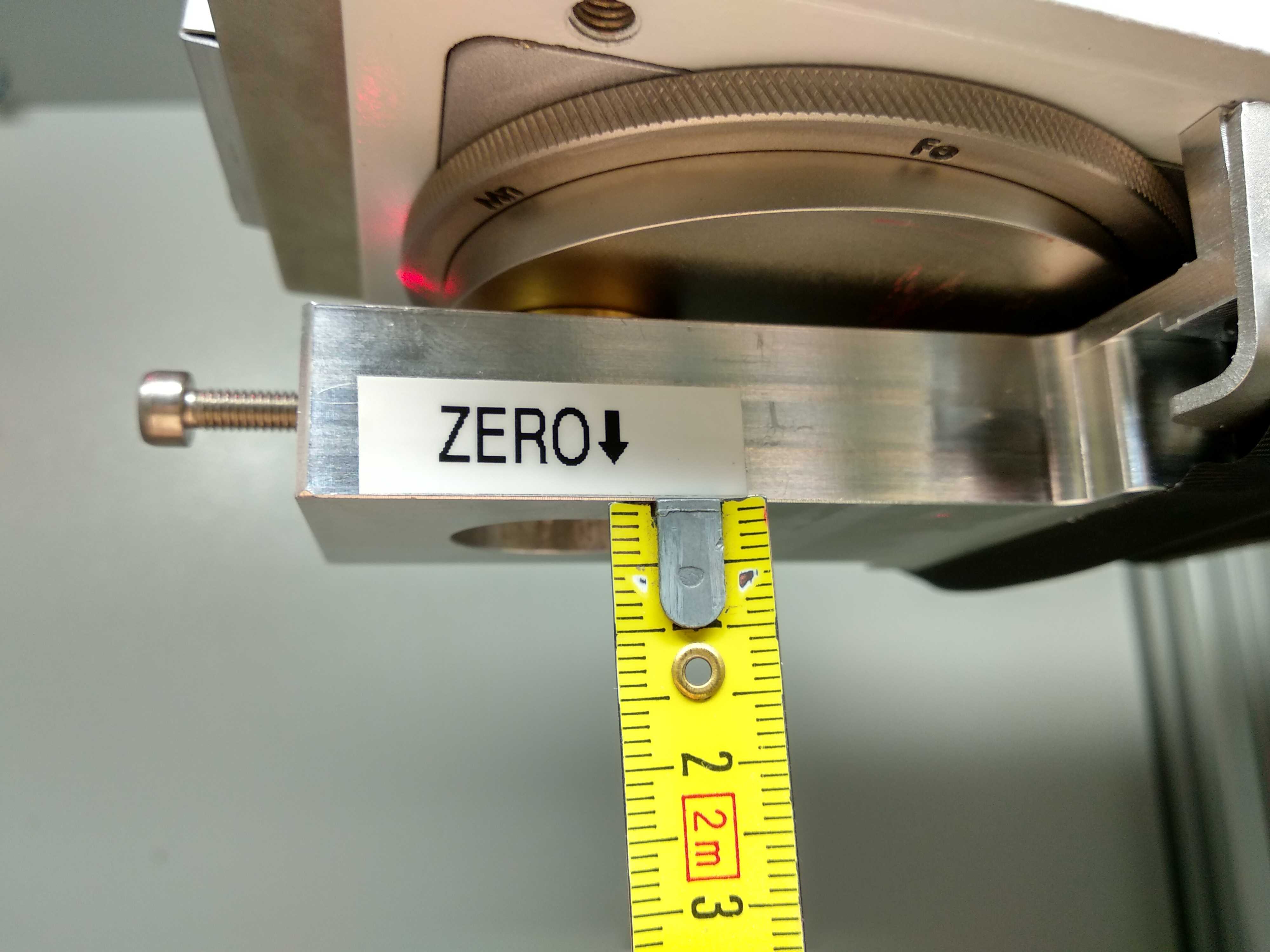
Figure 4: Zero position
Each beam output is protected by two independent shutters, the first (as seen in direction of the beam) is a electronically operated shutter (link) built into the tube housing and the second is a mechanical rotary shutter (also see here) integrated into the filter wheel. The rotary shutter is spring-loaded and in order to keep it open, the filter inserts themselves press against this spring.
The following filters are available: (Al 150 um, Al 400 um, Cu 400 um). Usually the Al 150 um filter is used, since the machine is calibrated to this filter (calibration procedure at CERN).
In case, the filter has to be changed, loosen the long set screw on the left of the collimator support, insert the filter with the narrow end first into the holder. While pressing it gently against the filter wheel, rotate the rotary shutter lever away from you until the filter slips into place. When you release the lever, it should stay in place. Make sure that the filter is fully inserted and then tighten the long set screw.