English | 简体中文
Introductory tutorial notes on OpenGL. Learn plug-in download, environment loading, graphics rendering principle, Shader... You can learn from the official Opengl documentation OpenGL Documentation
- Environment loading
In the initial learning process, to use Opengl needs to be equipped with a suitable environment. I am currently using
VS2019 + glfw3.3 + glm + glew2.1. Plug-in file download Opengl Working environment - Add
YourPath\glfw-3.3.4.bin.WIN32\includeandYourPath\glew-2.1.0\includeinProject->Properties->C++->Linker->General->Additional library directory.
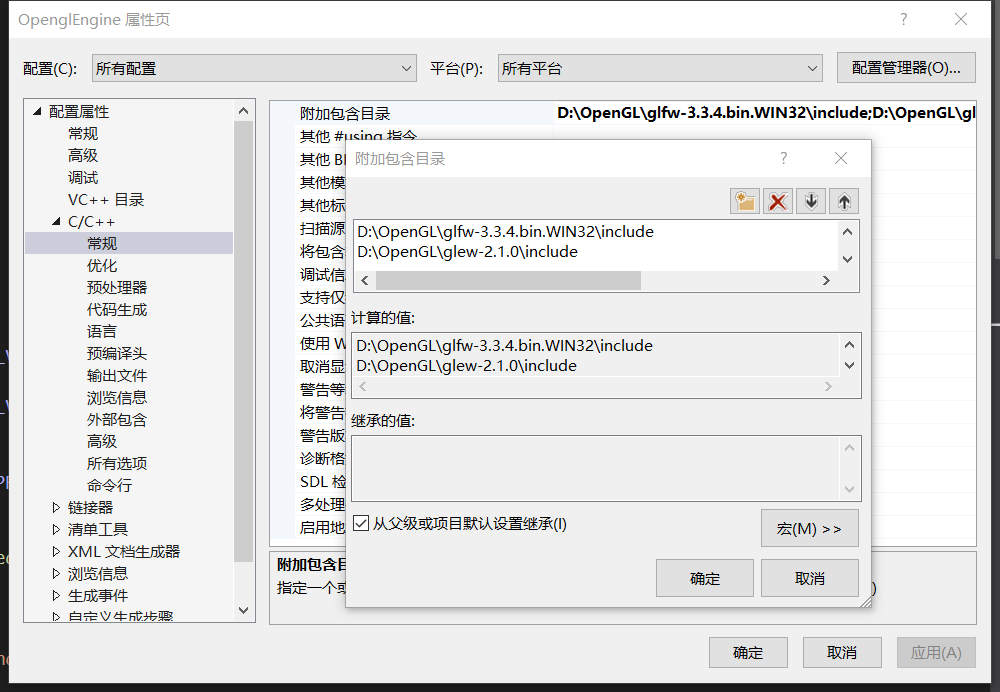
- Add
YourPath\glfw-3.3.4.bin.WIN32\lib-vc2019andYourPath\glew-2.1.0\lib\Release\Win32inProject->Properties->Linker->General->Additional Library Directory.
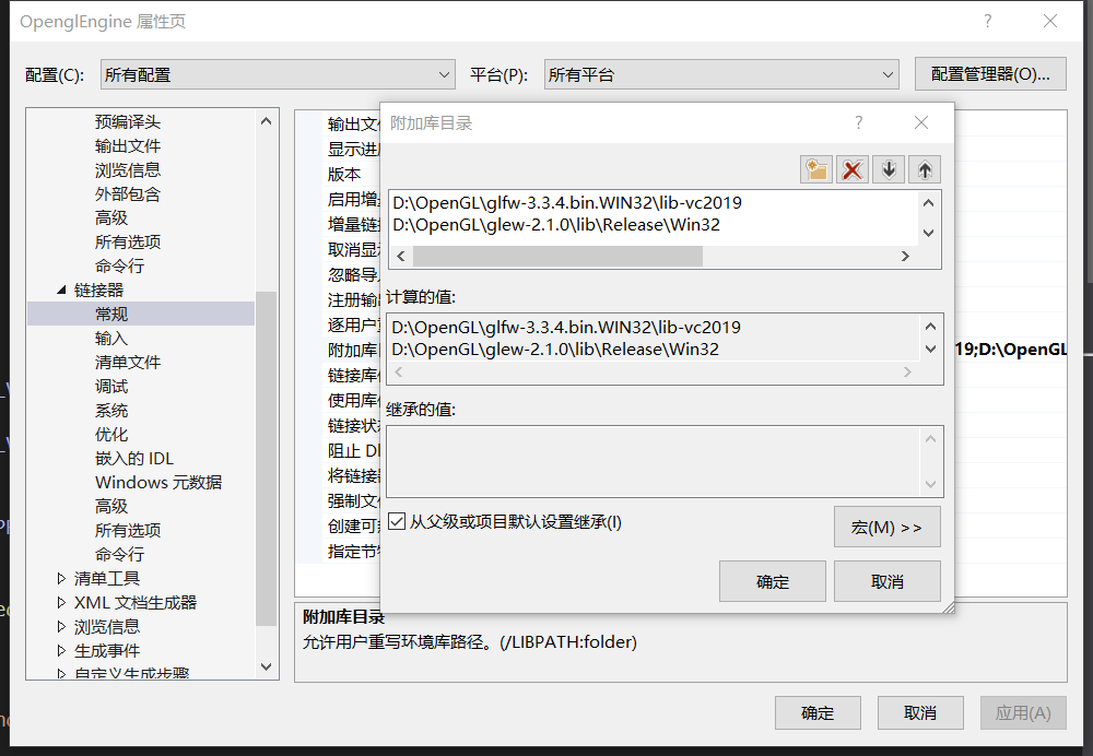
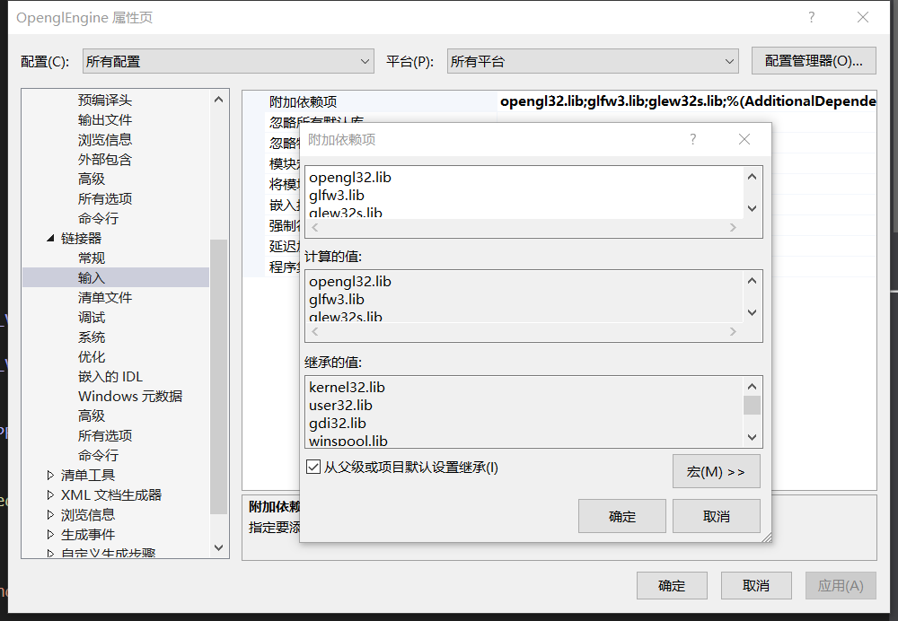
- Add
opengl32.lib,glfw3.libandglew32s.libinProject->Properties->Linker->Input->Additional dependencies.
The environment loading is complete, if it fails, please download [Glfw DownLoad] from the official website glfw download
You can quickly check the parts you want to know through the catalog.
| Module | File Link |
|---|---|
| Window | Window |
| Camera | Camera |
| Shader | Shader |
| Texture | Texture |
| Material | Material |
| Mesh | Mesh |
I will put some necessary and basic code that I have learned for review.
-
Initialization and window construction Regarding window construction, you need to define the window
/*Create window*/
GLFWwindow* window = glfwCreateWindow(800, 600, "OpenglEngine", nullptr, nullptr);
Then perform rendering and display. Of course, we need to use a rendering loop during the rendering process.
/*Canves window*/
glViewport(0, 0, 800, 600);

/*Rendering loop*/
while(!glfwWindowShouldClose(window)) {

  /*Color temporary block exchange*/
  glfwSwapBuffers(window);

  /*Get user button*/
  glfwPollEvents();
}
For more, please see the detailed comments in the source file Create Window
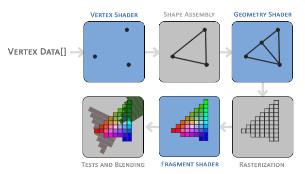
the schematic:
I try to use my understanding to explain clearly how an .obj file is loaded and used.
When an .obj file is read to the CPU, it will reach the GPU through a long distance. At this time, the digital coordinates parsed by the .obj file cannot be recognized (arr), we need to install it to an array coordinate that can be recognized.
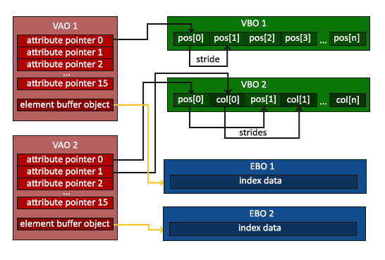
These arrs will be placed in the VBO after they reach the GPU. We need to bind this VBO to the VAO (GL_ARRARY_BUFFER), and plug it into the vertexShader through the VAO to draw the vertices.
The source code tells us that if we only rely on VBO + VAO to draw graphics, then the vertex coordinates will be repeated in the code, so we need to add EBO to rely on index coordinates (indices) to reduce the redundancy of the vertex coordinate code.
Below is a diagram of the relationship structure between VAO, VBO, and EBO to better understand their previous role and relationship:
Putting VAO into VertexShader we also need to operate vertexShader and fragmentShader, so we also need to write vertexShaderSource and fragmentShaderSource code in the code to tell the GPU how to draw these vertices.
First, we need to create VertexShader and fragmentShader, then insert the Source into it, paste the VertexShader and fragmentShader onto the shaderProgram, and then connect the shaderProgram to the Shader, so that the Shader can read the code in the Source!
After connecting, use the connected shaderProgram in the rendering loop, then bind the VAO to the Vertex Shader, use the vertex array in the VAO to draw the vertices, and then draw the graphics in the subsequent Shader.
- Uniform
Uniform does not pass Vertex through VAO, it is directly stuffed into Vertex, we need to find the position of Uniform in Cpp, and then pass the value. For example:
timeValue = glfwGetTime();
dynamicColor = (sin(timeValue) * 0.5f) + 0.5f;
/* Find the position of the uniform in the Shader */
int vertexColorLocation = glGetUniformLocation(shaderProgram, "vertexColor");
/* Insert ve4 in the corresponding position */
glUniform4f(vertexColorLocation, 0.f, dynamicColor, 0.f, 1.f);
Then manipulate these variables defined by Uniform in the Shader.
For more, please see the detailed comments in the source file Render principle
How to load pictures in the window through Shader? We can achieve this by passing Texture to VAO.
Here is the main point to talk about the principle, the first is to create the texture, the method is the same as that of the VAO VBO, there is no difference between using the corresponding API for creation and type binding, and then we can use the stbi_load function To load the picture, fill in and generate Mipmap. Below is the code, which is more helpful to understand.
glGenTextures(1, &texBuffer);
glBindTexture(GL_TEXTURE_2D, texBuffer);
data = stbi_load(_filename, &width, &height, &Channel, 0);

/* Flip the picture */
stbi_set_flip_vertically_on_load(true);
glTexImage2D(GL_TEXTURE_2D, 0, GL_RGB, width, height, 0, GL_RGB, GL_UNSIGNED_BYTE, data);
/* Open Mipmap */
glGenerateMipmap(GL_TEXTURE_2D);
Then Texture puts the loaded image into the VAO. In the VAO, 8 interfaces are prepared for the Texture to allow the Texture to insert the image. Different Texture inserts different images into different interfaces, and then the image can be superimposed.
As for how to implement the selection of texture insertion in different interfaces, please check the commented Texture Insert in the source code. The following is a demonstration of the Texture function:
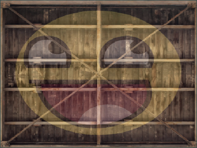
For more, please see the detailed comments in the source file Texture
To draw a 3D cube, we need to use the glm file, you can download it through Glm Download, or through the official download: GLm Official Download, then add glm to the C++ include directory as you did before configuring the environment.
How to put a flat 2D drawing into a cube? what should we do? Below I would like to illustrate with my method through my study.
Below I will put a schematic diagram from 2D to 3D:
.png)
We can construct Model Matrix, ** View Matrix **, ** Porject Matrix ** through this image. We put these three matrices into Vertex Shader Source through Uniform, and then multiply ** gl_Postion * *Come into 3D!
- Model Matrix
It is used to determine the state of this 3d cube, including his position, his distance (translate), his rotation around that axis... - View Matrix
It is used to determine the position of our observation, generally to the Z axis of viewMat -3, so that the camera can be in the center of the world! - project Matrix
What I understand is that it is used to standardize the space, and the distance and perspective projection of objects are completed by him.
Then we are using VBO + VAO to draw through vertices, of course if you have relevant indices you can use EBO to draw..
We haven't finished yet, thinking that Opengl can't tell which is the front and which is the back, so we have to let him detect the Z-Buffer, that is: if there is already something rendered in front, then don't render other things at that pixel..
glEnable(GL_DEPTH_TEST);
glClear(GL_COLOR_BUFFER_BIT | GL_DEPTH_BUFFER_BIT);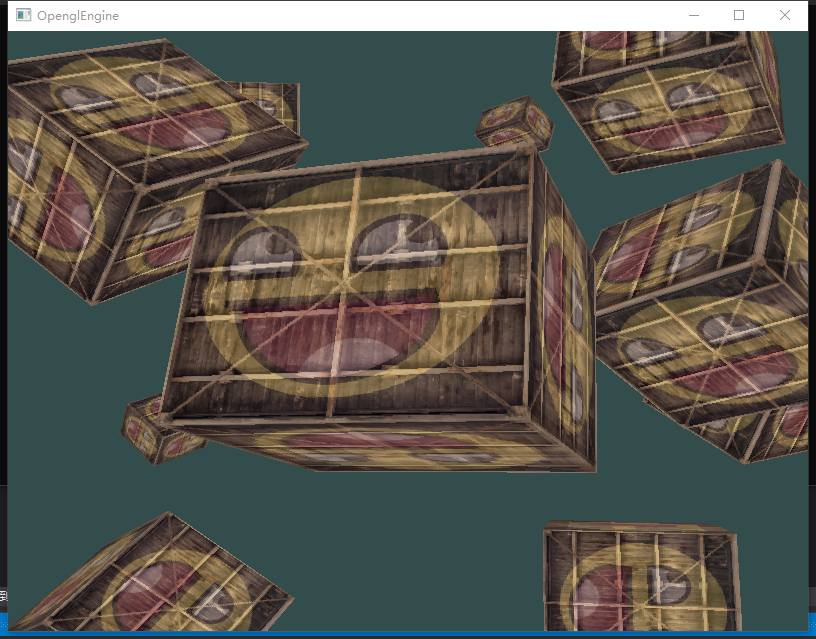
For more, please see the detailed comments in the source file 3D
Now we want to view the cube from different orientations by moving the mouse and entering keyboard actions. So what should we do?
-
How to achieve the camera's moving perspective by moving the mouse?
In fact, we can observe the cube from different positions by changing the View Matrix, but this is not complete, nor is it the full function of a camera, so we need to get the camera's Forward, Right, Up, and the world vector WorldUp. Their calculations are used to control View Martix.
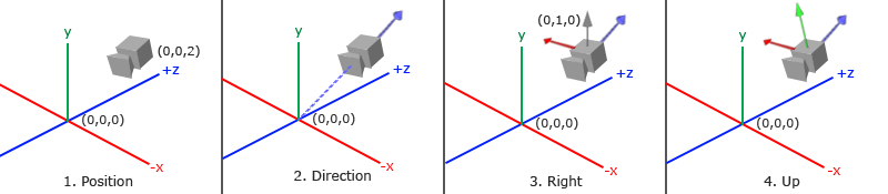
Of course, these can only determine the camera's perspective, so how do we use the mouse to make the camera 'head up' and 'turn its head'? We also need some angles: Pitch, Yaw. Then calculate Forward through some mathematical calculations, and then indirectly change the Forward of the Camera by changing Ptich and Yaw by obtaining the coordinates of the mouse.
It also changes the angle of the camera.
Get camera coordinates:/* Get the coordinates of the cursor in the window */ glfwSetCursorPosCallback(window, mouse_callback); void mouse_callback(GLFWwindow* window, double xPos, double yPos) { if (is_first) { prevX = xPos; prevY = yPos; is_first = false; } float dirX, dirY; dirX = xPos - prevX; dirY = yPos - prevY; prevX = xPos; prevY = yPos; camera->CameraMovment(dirX, dirY); }
Pitch and Yaw concept map:

For more details, please check the source file for detailed comments Camera.
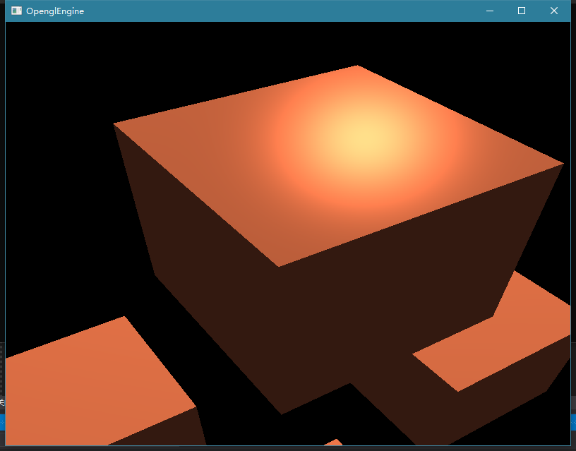
There are only textures on our cube without the most common lighting effects in nature, so how can we use Opengl to imitate the effect of basic lighting?
-
Fung Lighting/Diffuse Lighting
We need to reflect the shadow on the basis of direct light, as shown in the figure:

We need two data, one is the position of the light, and the other is the normal vector Normal. The normal vector can be passed in from the VAO through vertices, and the position of the light can be defined by itself and passed in through the Uniform. Next we need to pass the LightPos The light emitted from this position becomes a vector, then, we need to use (lightPos - FragPos), This FragPos is the position where the light shines on the object, (FragPos = vec3(modelMat * aPos).xyz), and then we multiply dot(Normal, (lightPos - FragPos)) to get the intensity of the diffuse light, and multiply it by LightColor. Get true diffuse light. -
reflection of mirror
Specular reflection is when you look at the cube, it reflects the bright spots of the light source for you, that is specular reflection, if the surface of the cube material is rough, then the reflected light source is a range, put the schematic diagram for better understanding:

We have obtained Normal and LightDir in diffuse reflection, then we now need to know the reflected light source vector (reflectVec) and the position vector of glasses (eyeVec), both of which are easy to get, reflectVec is the relationship between -LightDir and normal vector , and GLSL gives us the function to solve this problem,
(reflectVec = reflect(-LightVec, Normal)), and eyeVec is the same as getting LightDir, (eyeVec = normalize(eyePos - FragPos)), so we multiply reflectVec and eyeVec to get specular reflection, but specular reflection The effect is not very strong, The effect of specular reflection can be enhanced by doubling (pow(a, b)).
-
About normal vector Normal calculation
Normal = mat3(transpose(inverse(offsets[gl_InstanceID]))) * aNormal Why is this?
It is known from OpenGL that when the object is scaled irregularly, the normal vector will change. In order to solve such a problem, a model matrix needs to be customized, so this calculation is required.
Details: About the calculation of Normal
For more details, please check the source file for detailed comments basic lighting-vert , basic lighting-frag