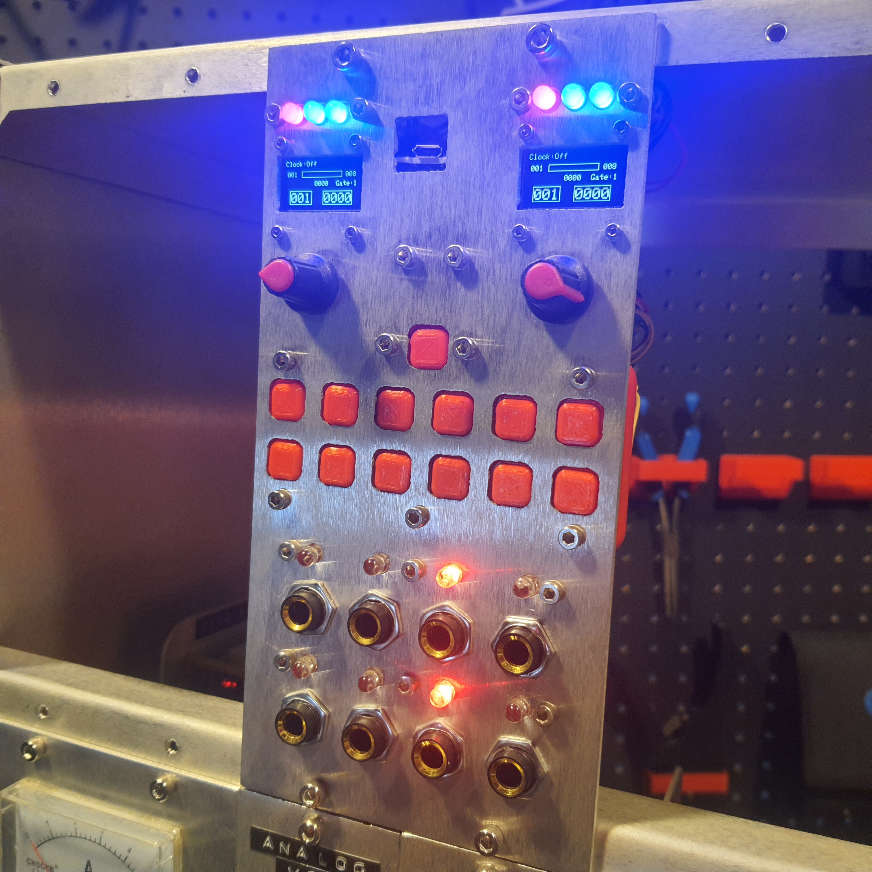
Right now this module is primarily a sequencer but also serves as a digital module software development platform. It has 8 inputs/outputs 2 of which are on a 12 bit DAC that has output circuitry to switch between 0 to 5 volts high resolution or 0 to 10 volts slightly less high resolution, 2 on PWM capable Arduino pins that have a voltage doubler to reach 10 volts, and 4 on analog input pins that can be used as analog inputs or digital outputs.
5 Volt: 150 mA
12 Volt: 10 mA
-12 Volt: 10 mA
20 x 5 CM (KOSMO)
| Part | Amount |
|---|---|
| MCP4922 DAC | 1 |
| TL074 OP-AMP | 1 |
| DIP14 Sockets | 2 |
| Prototyping board | 1 |
| SD Card module | 1 |
| SD Card 2GB or less | 1 |
| RGB Leds | 6 |
| Leds | 8 |
| Arduino Pro Mega | 1 |
| ¼ Jack Sockets | 8 |
| Rotary Encoder | 2 |
| OLED 128x64 | 2 |
| Knobs | 2 |
| Buttons | 13 |
| 10k trimmer | 2 |
| 5k trimmer | 2 |
| 2N3904 transistor | 2 |
| Power connector | 1 |
| Wire | Alot |
| Value | Amount |
|---|---|
| 1k | 21 |
| 10k | 10 |
| 100k | 4 |
| 470 | 8 |
Structure - Files on GitHub
| Part | Amount |
|---|---|
| M2 and M3 bolts, nuts ,and standoffs | many |
| Panel - “Panel.dxf” | 1 |
| Mounting shelf - “Shelf.dxf” | 1 |
| Led Mounts - “LedMount.stl” | 2 |
| RGB Led Mounts “RgbMount.stl” | 2 |
| Button Holder “ButtonHolder.stl” | 1 |
| Buttons - “Button.stl” | 13 |

| Digital Pins | Analog Pins | ||
|---|---|---|---|
| D0 | don't use | A0 | INPUT 01 |
| D1 | don't use | A1 | INPUT 02 |
| D2 | encoder 1 | A2 | INPUT 03 |
| D3 | encoder 1 | A3 | INPUT 04 |
| D4 | TRIG OUT A | A4 | free |
| D5 | TRIG OUT B | A5 | Button 11 |
| D6 | Led 01 | A6 | Button 12 |
| D7 | Led 02 | A7 | Button 13 |
| D8 | Led 03 | A8 | Button 14 |
| D9 | Led 04 | A9 | Button 15 |
| D10 | Led 05 | A10 | free |
| D11 | Led 06 | A11 | free |
| D12 | Led 07 | A12 | free |
| D13 | Led 08 | A13 | free |
| D14 | HIGH/LOW RANGE SWITCH A | A14 | free |
| D15 | HIGH/LOW RANGE SWITCH B | A15 | free |
| D16 | RGB LED 01 | ||
| D17 | RGB LED 02 | ||
| D18 | encoder 2 | ||
| D19 | encoder 2 | ||
| D20 | i2c SDA -oleds | ||
| D21 | i2c SCL -oleds | ||
| D22 | RGB LED 03 | ||
| D23 | RGB LED 04 | ||
| D24 | RGB LED 05 | ||
| D25 | RGB LED 06 | ||
| D26 | RGB LED 07 | ||
| D27 | RGB LED 08 | ||
| D28 | RGB LED 09 | ||
| D29 | RGB LED 10 | ||
| D30 | RGB LED 11 | ||
| D31 | RGB LED 12 | ||
| D32 | RGB LED 13 | ||
| D33 | RGB LED 14 | ||
| D34 | RGB LED 15 | ||
| D35 | RGB LED 16 | ||
| D36 | RGB LED 17 | ||
| D37 | RGB LED 18 | ||
| D38 | Button 01 | ||
| D39 | Button 02 | ||
| D40 | Button 03 | ||
| D41 | Button 04 | ||
| D42 | Button 05 | ||
| D43 | Button 06 | ||
| D44 | Button 07 | ||
| D45 | Button 08 | ||
| D46 | Button 09 | ||
| D47 | Button 10 | ||
| D48 | free | ||
| D49 | SPI SD Card CS | ||
| D50 | SPI MISO - DAC -SD | ||
| D51 | SPI MOSI - DAC -SD | ||
| D52 | SPI SCK DAC -SD | ||
| D53 | SPI DAC CS |

The output voltage range of the analog outputs is software adjustable for 0 to 5 volts high resolution or 0 to 10 volts slightly less high res.
8 free pins on Arduino
As of August 12 2022 the software requires the following libraries:
Streaming.h - https://github.com/janelia-arduino/Streaming
SdFat.h - https://github.com/greiman/SdFat
Adafruit_GFX.h - https://github.com/adafruit/Adafruit-GFX-Library
Adafruit_SSD1306.h - https://github.com/adafruit/Adafruit_SSD1306
Encoder.h - https://www.pjrc.com/teensy/td_libs_Encoder.html
MCP_DAC.h - https://github.com/RobTillaart/MCP_DAC
Software is definitely in early versions right now and I'll probably update it a quite few times in the future. If you have suggestions let me know.