Torque OSWEC hydraulic PTO #247
Comments
|
@NicolasQu both of those observations should be correct. If you increase the surface area, you are increasing the force applied on the PTO, and thus the power. If the flap has a positive velocity, the power output should also be positive, and vice versa. |
|
@kmruehl Thanks for your reply! |
|
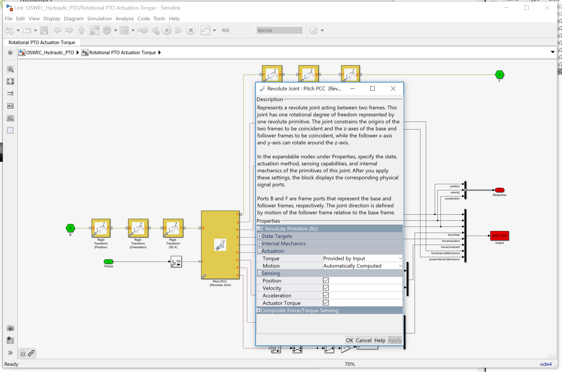
@NicolasQu, I looked into this issue a bit, and I think this has to do with a few different factors. The first being that all outputs from joints/constraints are reported in the body fixed local coordinate system, not the global coordinate system. If you go under the mask for the PTO blocks you will see a series of Simscape Multibody Rigid Transform blocks in combination with a Simscape Multibody Revolute Joint (for the OSWEC) and a Simscape Multibody Prismatic Joint (for the RM3). Simscape Multibody specifies a default DOF for each joint, and WEC-Sim rotates these joints to the appropriate orientation. As a result, depending on where you are looking at the signal, it may not have been re-oriented yet. However, all dynamics/loads saved to the output data structure should have the correct body-fixed orientation. Based on your post, the most likely reason for the observed sign discrepancy is that the WEC-Sim actually does not directly output the internal force due to damping alone because: If your model has |
|
@kmruehl , thank you for your explanation. There is however still something I don't understand. When I do the same for the RM3 device with hydraulic PTO, I found an optimal value for the piston area with an optimal mean absorbed power of 105 kW, which seems more logical. |


|
@NicolasQu it does seem unusual that the power for the OSWEC is increasing and does not show an optimal value based on piston area (within the plotted range). These application cases were developed to demonstrate functionality of the WEC-Sim code, but the devices and ptos were not optimized so it's hard to provide insight. I recommend running a larger range of piston areas for the OSWEC because I would expect its loads to be larger than those on the RM3. The other important factor to note is that the OSWEC model doesn't account for friction or drag which will likely be dominating physics, and thus WEC-Sim will overpredict the power output with their omission. |
|
@NicolasQu does this answer your question? |
|
@kmruehl the loads are indeed larger for the OSWEC than for the RM3, but the absorbed power going to 600 kW seems very high, especially when comparing with the absorbed power for OSWEC with a linear damper which goes to ca 260 kW. If the range of piston areas increased, I get an error for excessive pitch angles. When I added one minus sign in the Simulink model calculation of the PTO-torque of the hydraulic OSWEC, this is the result I got: |

|
@NicolasQu, sorry for the delayed response. I finally had some time to delve deeper into this issue and came to the same conclusion you have; there is indeed a sign error for the OSWEC Hydraulic PTO application case. I think this is due to the inclusion of Rotary to Linear Adjustable Rod and its sign convention (since that's the only difference between the RM3 and OSWEC Hydraulic PTO cases). My question for you is where did you add the minus sign for the PTO-torque in the OSWEC Hydraulic PTO case? |
|
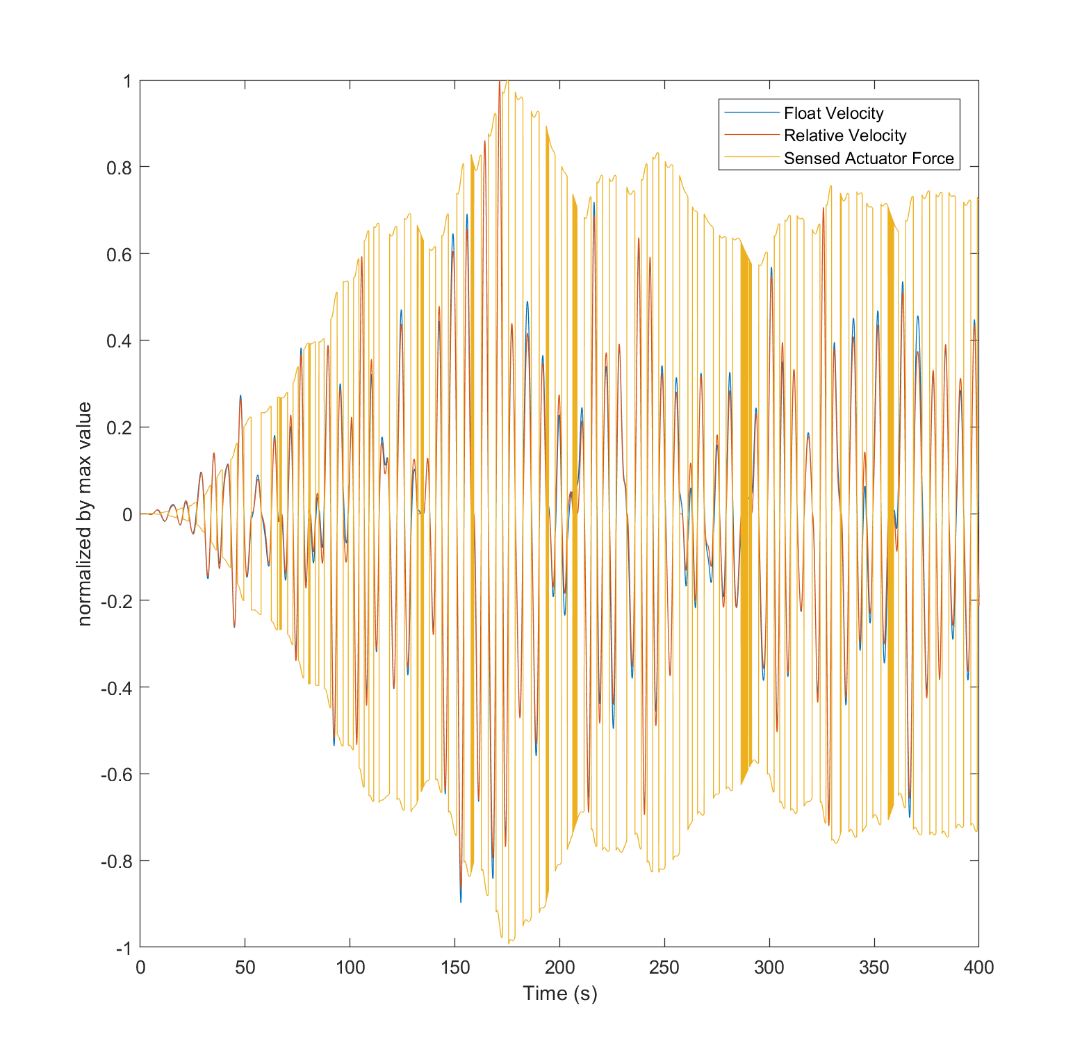
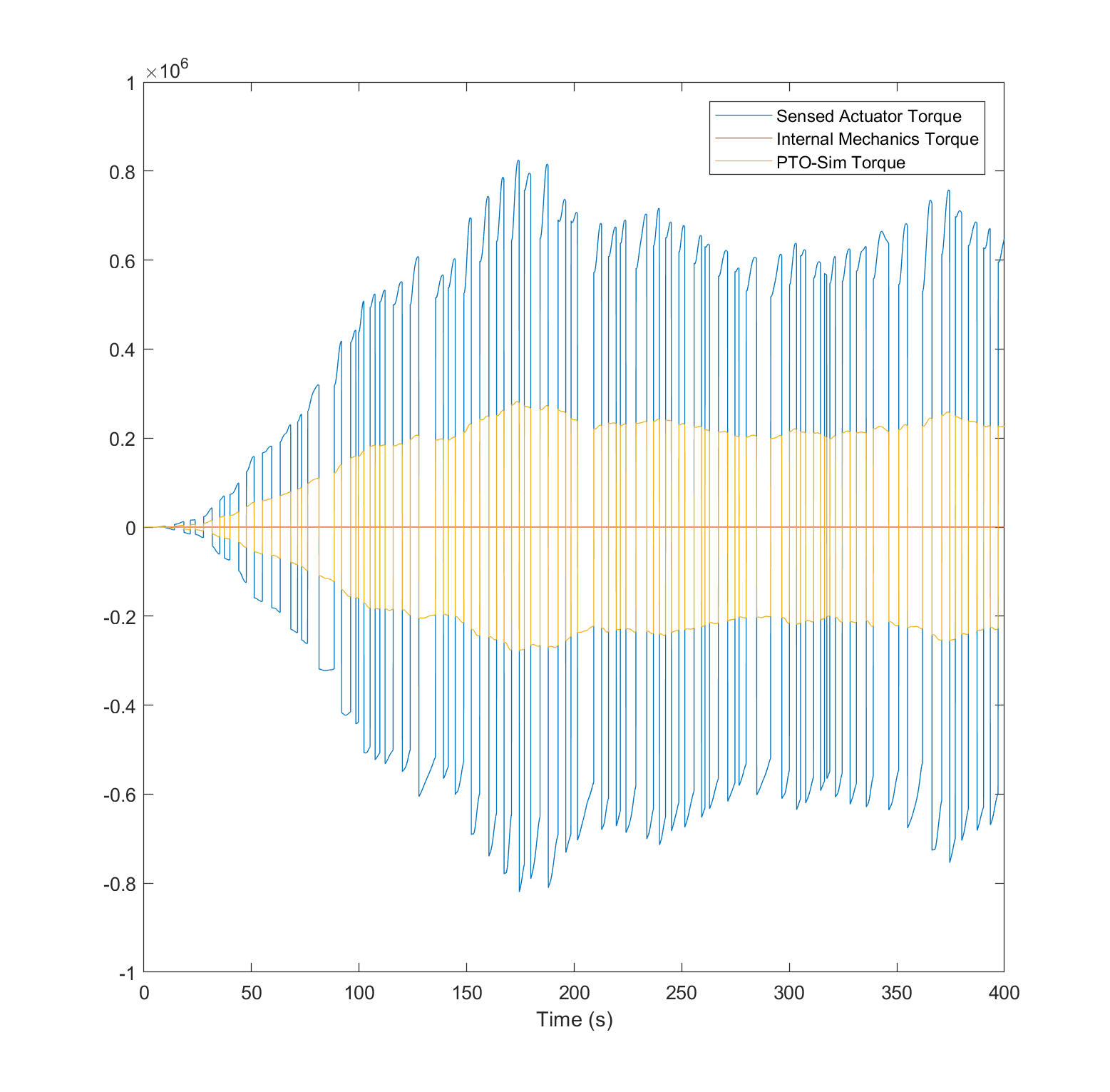
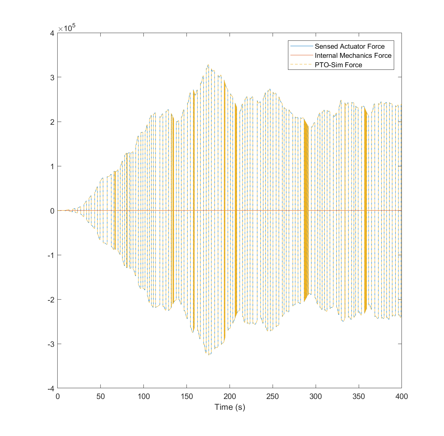
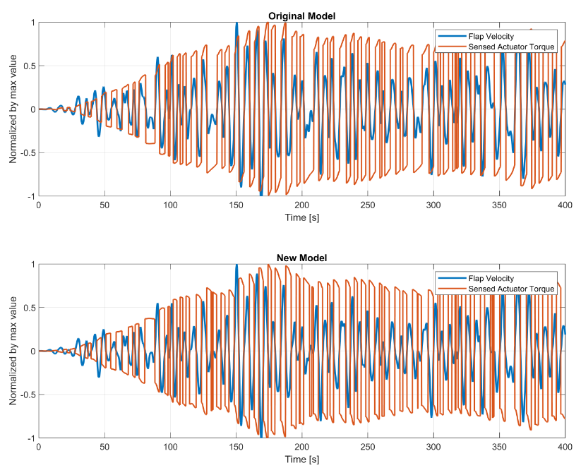
Note to self... OSWEC Hydraulic PTO: Flap Velocity, and Sensed Actuator Torque. The torque and velocity have the same sign: RM3 Hydraulic PTO: Float velocity, relative velocity, and Sensed Actuator Force. The force and velocity have opposite signs: Sensed Actuator Torque is the torque applied to the PTO and 'sensed' by the Simscape Revolute Joint: For the OSWEC, the Sensed Actuator Torque ( For the RM3, the Sensed Actuator Force and PTO-Sim Force have the same sign and different magnitudes, and the Internal Mechanics Force is zero (for pto.c and pto.k set to 0): Added a negative sign internal to the pto-sim subsystem, this corrects the sign error for the Sensed Actuator Torque Need to resolve issue to correct both the Sensed Actuator Torque ( |


|
Was this issue solved in new version? |
|
I spent some time working on this issue and I found an error in the Rotary to Linear Adjustable Rod block in PTO-Sim. The error is in the calculation of the torque of the hydraulic PTO. The hydraulic cylinder exerts a force on the flap, and this creates a torque on the pivot of the flap. I recalculated the torque by using a different equation based on the figure shown below:
The torque in the point O can be calculated using this equation:
The torque obtained using the new formulation and the flap velocity have opposite signs, as it was expected. This new formulation corrects the original results, when the torque and the flap velocity had the same sign.
|


|
@jleonqu Thank you for documenting the issue and resolution. Please submit a PR to resolve this issue, and then we can close it out. Thanks again! |
Hi!
I have a question about the hydraulic PTO for the OSWEC example.
When I increase the values of the piston top and bottom area, I saw that the power keeps increasing.
When I plot the velocity of the flap in pitch together with the torque applied by the PTO (calculated inside 'rotary to linear adjustable rod'), I noticed that the torque is positive when the velocity is positive, and negative when the pitch velocity is negative. Shouldn't this be the other way around?
Thanks in advance!
Regards
Nicolas
The text was updated successfully, but these errors were encountered: