Programming an ATTINY85-20PU on a breadboard with Arduino ISP
Here's a quick video of it in action:

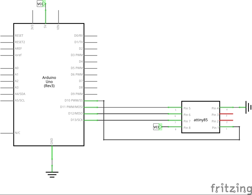
The objective here is to setup an ATTINY85-20PU chip on a breadboard, and program it using an Arduino operating as an in-system programmer.
I'm running Arduino 1.6.1 (MacOSX), so I first needed to add ATiny support for Arduino IDE 1.6.x. I always prefer to clone rather than download zips so I'm able to work on the source if necessary. In these steps ${sketchbook_folder} refers to my actual sketchbook folder location.
git clone git@github.com:damellis/attiny.git
cd attiny
git checkout -b ide-1.6.x origin/ide-1.6.x
mkdir ${sketchbook_folder}/hardware
cp -R attiny ${sketchbook_folder}/hardware
After restarting Arduino, I now have new Tools menu options.
Setup the Arduino ISP. Note in this case I'm using an Arduino Uno as the programmer:
- Select
Tools > Board > Arduino Uno - Select
Tools > Port > (correct port for Arduino Uno) - Upload Examples/ArduinoISP sketch to Arduino Uno
- Select
Programmer > Arduino as ISP
I went with the basics:
Tools > Board > ATtinyTools > Processor > ATtiny85Tools > Clock > 1MHz (internal)
Depending on the state of the chip, this may not be necessary. But if in doubt, burn it again:
- Select
Tools > Burn Bootloader
I'm testing with TinyBlink which runs LEDs on digital pins 0 and 1.
- Open desired sketch
- Select
File > Upload Using Programmer(or shift-click the normal upload icon)
Crickey, it works.
The ATtiny85 can use an external clock, but by default it uses an internal oscillator. The internal oscillator runs at 8 MHz, prescaled down to 1 MHz by default.
The clock settings are in the fuses. I used avrdude to read the settings:
$ avrdude -c stk500v1 -p attiny85 -P /dev/cu.usbmodem14521 -b 19200 -U lfuse:r:-:i

avrdude: AVR device initialized and ready to accept instructions

Reading | ################################################## | 100% 0.05s

avrdude: Device signature = 0x1e930b (probably t85)
avrdude: reading lfuse memory:

Reading | ################################################## | 100% 0.02s

avrdude: writing output file "<stdout>"
:01000000629D
:00000001FF

avrdude: safemode: Fuses OK (E:FF, H:DF, L:62)

avrdude done.  Thank you.
The engbedded fusecalc site is invaluable for decoding or calculating fuses values.
It confirms that E:FF, H:DF, L:62 are factory defaults: 8 MHz internal oscillator with CKDIV8 prescaler: so it is running at 1 MHz.
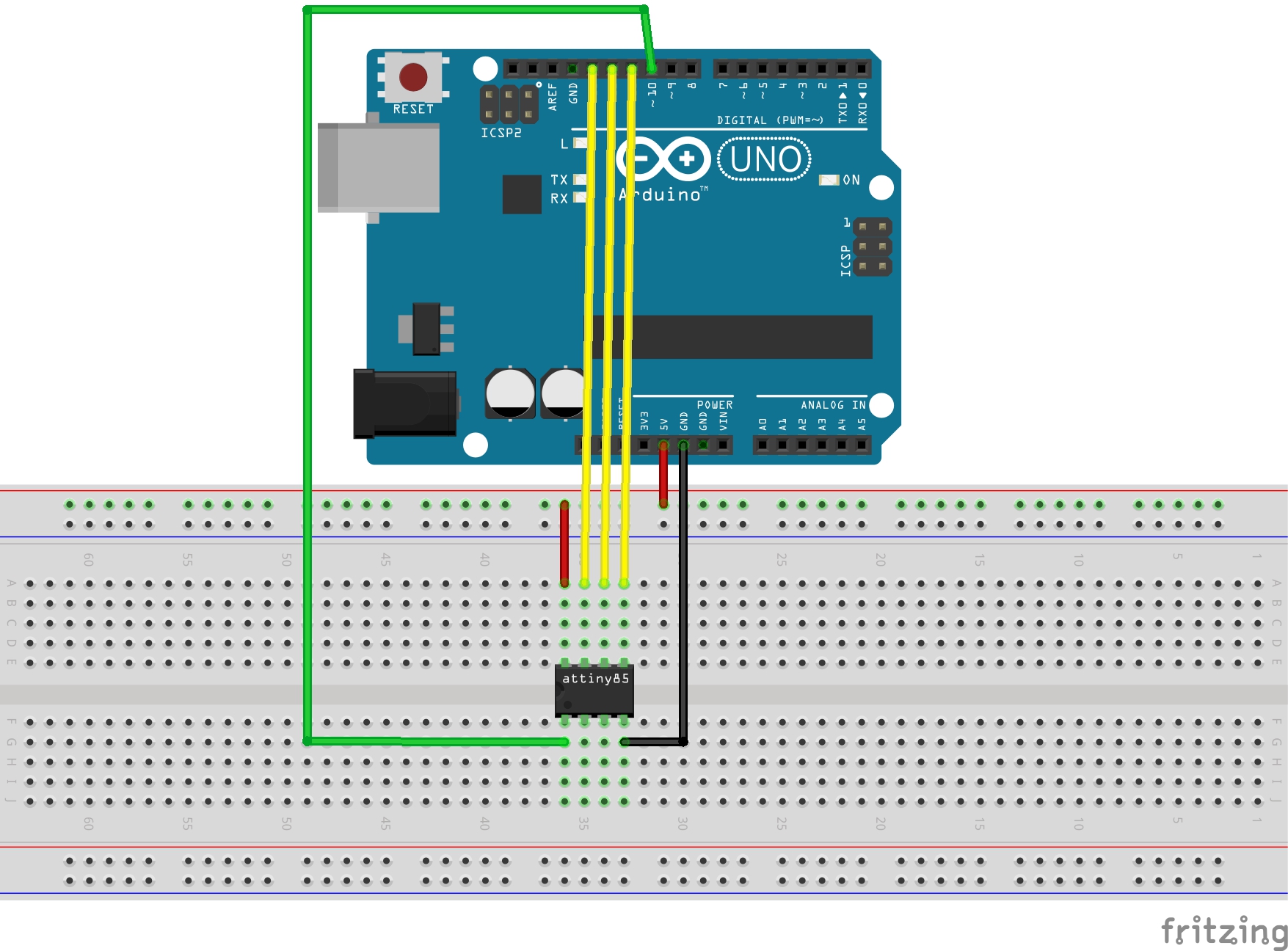

NB: in the breadboard, pins 5 and 6 are wired LEDs. These are for a test scketch and not required for programming (but neither do they interfere with buring the bootloader and uploading a sketch).
- LEAP: TinyBlink - a simple ATtiny test sketch
- LEAP: ATtinyProgrammingShield - a programming shield version of this project
- Atmel ATtiny85 Product Info
- ATtiny microcontroller support for the Arduino IDE
- Programming an ATtiny w/ Arduino 1.6 (or 1.0)
- Programming an ATtiny with Arduino ISP
- engbedded fusecalc