i_en_dataflow
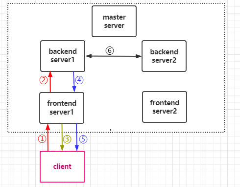
- In the figure, there are a master management server, several backend servers, several frontend servers (ie gateways), and several clients. (Note: There is a socket connection between every two server groups, not shown in the figure)
- The client sends a message to the server: After ①, it reaches the frontend server, calls the
protoDecodefunction, if the message is to this server, it callsmsgDecodeand executes the corresponding Message interface. If the message is to the backend server, copysessionBuffand encode it together, and after ②, callmsgDecodeafter reaching the corresponding backend server, and execute the corresponding message interface. - The frontend server sends a message to the client: After calling the
protoEncodefunction for encoding, it passes through ③ to reach the client. - The backend server sends a message to the client: After calling the
protoEncodefunction encoding, adding the uid array information, after ④, the uid array information is parsed after reaching the frontend server corresponding to sid, and the message is sent to the corresponding client. That is, after ⑤, to the corresponding client. - Between servers, the developer rpc calls: ⑥.