Arduino mega shield #1
Comments
|
Thanks.
Minor: I don't think it'll make any difference to your shield, but you might wish to check the differences between "Earth", "Ground", "Chassis", "Common" and "0V" as well as named nodes such as "0VA" and 0VP" which are both 0V but for different sections. Just in case anyone else has the same problem: My ISP (Sky) had turned on its family filtering shield and blocked images (jpg, png) from Github (including yours) without me knowing, it just timed-out the images. Took a while to find out it was them. Filter is now off. |
|
Yes, it is really necessary to filter out schematic porn because we know what it does to our brains! Thank you for the excellent analysis re: grounding and loops. I fondly remember installing Univac 1100/80 systems in the late 70's with 8" wide copper strips on the sub floor to tie the logic grounds to. Lot of fun isolating logic from frame ground when a system is spread over 3 floors. Not fun to troubleshoot spurious problems when the grounding was wrong. |
|
That's some bad drawing by me, only my forth day drawing schematics, when i flip the connectors in the drawing it flips the numbers. your right about the earth,common and 0v, i know what i mean but its not clear on my drawings. What would be the best way to label P2 connector. |
|
My tower PC will not reliably run my CNC controller because 0V is connected to Earth at both ends and hence it has a ground loop via the USB. Noise in that tends to corrupt the USB comms. But my laptop works fine because it's 0V is not connected to ground. @gerritv @adambrum What electronic CAD software do you use? |
|
Tried fritzing, easy but not a huge library of parts now on EasyEDA still to try the PCB part . I have Bcnc running on a Raspberry pi3 so far so good |
|
I was using CamBam to generate gCode but will likely switch to the free HSM 2.5. Might try Fusion360 as well. I hope to get my cnc going again soon, which should spark a re-write of GrblPanel as it has become a bit of a rats nest over time :-( It works but it can be challenging to add features, of which there is a growing list of needs. |
|
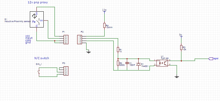
Drawn up all the inputs now, |

|
@adambrum Are you planning on making this input/output conditioner a separate pcb? That in my view is more useful than one tied to a specific processor. It would be useful now with the Arduino's and later on with the ARM versions. |
|
Originally i was planning on a I/O board connected with a 26 way ribbon cable and a separate shield for uno , mega or an ARM board when there out then went back to an arduino mega shield. Now you've raised the same thought an I/O board would be easier so why not, cost is negligible . |
|
I still think the optocouplers are rather pointless if there is no way to actually isolate the two sides. and instead of a 10R resistor (it'll just catch fire if something shorts) use a voltage regulator that is current limited and short circuit protected |
|
It might help @adambrum to draw an imaginary line down the board through middle of the opto's. No trace or wire should cross the divide. |
|
Updated now with 0-10v added, think i have managed to isolate the circuit. From looking around google it looks like standard optos work with PWM. I have added a six way header for an external relay board, these are optoisolated and are probably cheaper to buy than make. I will add some holes to the Pcb so it can be mounted with standoffs.
Just the STEP,DIR and Stepper enable to be added, Any thoughts ? |


|
the 5V in P11 needs to be the arduino 5V or it won't work |
|
Yup i can see what i have done there |
|
@langwadt - I was drawing up the same comment...
You'll need arduino-side power for arduino-side signals. Also... As @biasedlogic said, GRBL has an issue with jitter and delay being added to the STEP and DIR signals and he suggested using the Analog Devices (AD) digital isolators instead of Opto-isolators. I've not yet been able to find a spec. for GRBL's tolerance but think that 20Mbit/s opto-isolators should be as fast as the AD digital isolators and much cheaper. |

I'm not sure what you mean. The digital inputs are fully isolated if you use external/separate power for the switches. If you don't, and tap the 12V from the Arduino, you still get at least better immunity against EMI, but you are not forced to. @cncpaw: iirc the direction pin is asserted just before toggling the step pin, of that's the case not many optos are up to that. |
|
altered the drawing again, added a 5v from the arduino to the relay header and looking at some posts for the relay board its needs 5v plus the digits signals and 5v,gnd from an external supply with no gnd from the arduino because of the optos. |

|
Hi Everyone, Trying to follow this thread as I have been experiencing noise related issues with my CNC Lathe build but the detailed electronics are more than a few fathoms over my head ... :-) You made a comment a few days ago that I was hoping you would expand on. "(I'm wary of commenting in this issue because it is no longer a problem in GRBL ...)" I'm using an Arduino UNO and shield from zyltech with GRBL v1.1. Did I understand you correctly that GRBL has somehow found a way to eliminate the noise problem in their code ? If so would you please point me to where I can find more information on this ? Thanks to everyone for sharing your knowledge so freely and all the hard work. Jay |
What I believe @cncpaw meant is, it's nothing to solve in code, it's got to be solved in hardware and so it should not be discussed in a software issue thread... |
|
For the step/dir is it something like this were looking for ? http://uk.farnell.com/toshiba/tlp118-e-o/optocoupler-3-75kv-20mps-soic/dp/2075566 |
|
That could/would do, but considering you need a couple of these, you may be off cheaper to just go for http://uk.farnell.com/analog-devices/adum7440arqz/ic-isolator-digital-quad-16qsop/dp/1827342?ost=ADUM7440ARQZ (pulse skew, and that's what counts here, <25ns) or http://uk.farnell.com/analog-devices/adum7440crqz/ic-digital-isolator-40ns-16qsop/dp/1858062?ost=adum7440crqz (if you want pulse skew <5ns) These are 4-channel with matched propagation, so you actually save on parts and get better reliability for the control signals. Just route DIR/STEP through same chip. For other digital outputs, or for drivers that need 5V supply, (there's also a sister part for inputs) you may find this one interesting: |
|
What about this one, i would like to keep it all in dip packages. i like the last one, could be good for the relay outputs, i think they need 70ma per channel. I noticed earlier that you went to Karlsruhe, been there myself a few times, my main office was just up the road in Bretten |
|
GBP7.94 each is a bit steep??? |
|
DIP is so yesterday... And, while it is extremely fast, it's also 4x more expensive, per channel, than the simplest ADuM... |
|
I know, might need to rethink the packages, I was trying to keep it easy to assemble, might have a go at soldering some surface mount to see how hard it is. |
|
@adambrum IMO surface mount is in many cases easier than through hole And once you have all that stuff on a pcb there is little reason not to put the MCU on there as well |
I disagree. Implementing MCU agnostic means that you are not re-designing the difficult' stuff every time you need/want to change MCU's. Just like the db25 style breakout boards, you are free to choose the computer, controller and drivers. |
|
@adambrum @JayPerez1 DIR STEP timing tolerance Section of code determining DIR-STEP spacing Extract of C-code from ISR(TIMER1_COMPA_vect) Disassembly of compiled extract @biasedlogic - I don't see how pulse skew need be less than 25ns. |
|
@gerritv you wouldn't have to redesign anything, just copy paste, and a footprint for an mcu is practically free. and it avoids the all too common hair ball of wires that does nothing for reliability. it would be easy to move the setting of the direction pin to the end of the interrupt or even to when a new segment is loaded, that would remove the need for silly skew requirements |
I'm sorry, if I was misleading. I didn't mean it needs to be less than 25ns, but that the chip I linked to has a skew of under 25ns and that it's the skew that counts and not the absolute transfer delay. Many "A4988" boards have actually a HR4988 chip, a chinese clone/development, for which setup times are an unknown parameter altogether, but that's another story |
|
Your all losing a me a bit here but i found some data on the drives im using.
|

|
@adambrum @biasedlogic My "simple" but limeted solution would be to replace with No change in code size and the time between edge transitions becomes 14 cycles = 875ns, excluding both of the out instructions, giving 100ns for isolators and 100ns margin with DRV8825. |
|
Had an idea and pulled my drive apart as its already optoisolated. |

|
@cncpaw I think moving sei() before setting the steps is dangerous with an overlap of interrupts you risk using an "old" st.step_bits or jitter. if you need more setup time on direction use STEP_PULSE_DELAY that's what it is there for |
|
Just joking but old school method (used in different format on Univac 1100/80's to calibrate clock signals between cabinets) http://www.newark.com/w/c/semiconductors-ics/clock-timing-frequency-management/delay-lines/prl/results?st=delay+line Gerrit |
|
I saw STEP_PULSE_DELAY in config.h, but wasn't completely sure what it was for. Surprised nobody has mentioned it before and hence wonder if it has an unmentioned downside or using it still rules out using slower/cheaper opto-couplers in the STEP/DIR/ENABLE paths, such the 5us setup in leadshine. |
|
@cncpaw the leadshine drivers most likely have optocoupler buildin so there is no reason to yet another layer of isolation. Slow enable shouldn't be an issue, slow dir is taken care off by STEP_PULSE_DELAY at tiny cost of an extra interrupt |
|
So whats the thoughts on isolating the STEP/DIR, i know with the drives im using theres no point but not all drives are going to have internal protection. Looking around the leadshine drives are being used on a lot of builds with no problems so im thinking the high speed opto should be more than capable. The ADUM are coming in at around £3 each for dual channel |
|
Thanks biasedlogic,
I found this thread using a Google search so never really noticed what
thread it was in. Perfectly obvious now that you pointed it out.
On Sep 25, 2017 1:27 AM, "biasedlogic" <notifications@github.com> wrote:
Did I understand you correctly that GRBL has somehow found a way to
eliminate the noise problem in their code
What I believe @cncpaw <https://github.com/cncpaw> meant is, it's nothing
to solve in code, it's got to be solved in hardware and so it should not be
discussed in a software issue thread...
—
You are receiving this because you are subscribed to this thread.
Reply to this email directly, view it on GitHub
<#1 (comment)>,
or mute the thread
<https://github.com/notifications/unsubscribe-auth/AdejyGNkydDG69NCPpPf_Kc9PFVSm-joks5slzm7gaJpZM4Pg8Mc>
.
|
I consider this interface as secondary priority for isolation. Usually, at least for what grbl is good for, the drivers are physically close to the grbl controller, and the wiring between them is short and does not have to run long stretches parallel to motor power wiring. It's rather easy to get good ground across. |
|
I'm drawing up isolation schematics for EN/STEP/DIR and will upload those and the schematics for my CNC in a day or so, to use as you wish. I'm assuming STEP_PULSE_DELAY will allow use of cheaper transistor-output isolators (~2us delay). |
No, but don't forget, that the actual microprocessor uses plain serial port, and isolating ttl-level RS 232 is rather easy. This would mean using external usb to ttl serial board, omitting the usb on the Arduino board completely and putting isolation between the usb-serial and the Arduino. |
|
Been tinkering around changing the schematic to use smd parts just need to find a replacment for the input optos and the diode. Also looking back at the shield Luben111 made would there be any advantages to adding a 74hct245p buffer to the step/dir ? Thanks Adam |
|
@adambrum I'm not that great fan of the buffer in this application, we are talking about a shield to a cheap µC board. This buffer does not offer real protection for the connected PC in case of a surge, it might protect the Arduino. But it's harder to replace a fried SMD buffer than to swap out a $10 arduino board, and the Arduino board is sold on any each street corner. If you are into expanding the board, I'd rather invest the effort into putting an USB-to-TTL-serial chip on the board, with a galvanic separation (opto/adum) on the serial side, to offer some real protection and ground separation for the control PC. |
|
Looks fairly easy to convert usb to serial than add an opto. I will try and knock up a quick schematic |
|
by far the easiest and cheapest would be to add a 6 pin header for one of the numerous ftdi etc. usb-serial cables |
|
Just a thought if we go this way the arduino is going to have to be powered separately so another power supply needed, I dont think we can use the same 12v supply from the I/O board as we have just isolated it from the arduino. or could add an isolated dc-dc converter |
|
FYI I uploaded the schematic of my CNC controller into a new issue for use as you see fit. This isolation issue is becoming ironic. The USB/RS232 module on the arduino has problems meaning that control programs need to use schemes like character-counting to achieve high speed. Isolation is best placed in the RS232 path. So it seems well worth doing, yet do that and the arduino becomes an ATmega328 with a resonator and connectors. Might as well make a bespoke ATmega328 board? Avoid the CH340 type USB/RS232 modules. Problems with them have been mentioned before in GRBL. FTDI-chips are recommended. If isolation is moved from the Arduino's IO to its RS232, then the arduino's power comes from the stepper drivers, suitably regulated but it need not be isolated. Just be careful with grounds and supply noise. |
|
It would be quite easy to make a 328 board now but im still intending to use the mega and i have a feeling that as soon i get this finished a 32 bit grbl will be released. Good to know about the CH340 chip that was the one i was looking at. |
|
been looking at the Adum4160 usb isolator, might be easier than usb-serial-isolation. Could this be a solution ? |
|
Several board are available based on that chip. Typical price about $15 or £30 or more. Doubtful a board based on it could be made any cheaper. If sold in quantity it would need to meet EMI regulations. |
|
Hi All, |
This is continuing on from the discussion on the GRBL limit switch issiue.
gnea/grbl#96
Hers where i got to on the limit switch wiring.
The text was updated successfully, but these errors were encountered: