Add IMU reference frame #22
Comments
|
Ran across this problem recently! You are clearly ahead of the curve here! We mount our IMU's in various orientations so this would be infinitely useful! In the absence of a setting, we could assume that sensor data needs to be in the base_link/base_footprint! This is what our good friends at robot_pose_ekf did :). |
|
Yeah, sorry about that. As it is now, any IMU data that is received is transformed into the frame specified by the base_link_frame parameter, so if you have your IMU mounted a certain way, you should be able to define a static transform from base_link->imu_frame and have it do what you want. Absolute orientations are best integrated differentially, so that may not be much of an issue, but an IMU that is rolled over on its side will incorrectly report angular velocities if they're not transformed. Is this a high priority for you all? |
|
Hmm...I did have a imu_link -> base_link tf being published. My base_link_frame parameter is correct to be the default. However, the IMU was still not being transformed. I'll check on it again to make sure I was doing things right. |
|
Interesting. Any chance you'd be willing/able to shoot me a bag file so I can debug? If so, just use my username at gmail. Is it orientation, angular velocity, or acceleration data that doesn't appear to be getting transformed? |
|
Yes! I'm tracking this down as we speak. If I get stuck, I might need some help. I want to make sure I'm not doing something dumb. |
|
Are you still having issues with this, @pmukherj? I'm debating how I want to handle this issue. Part of me thinks that the current behavior (just transforming everything into base_link) will work for most people, but I can think of cases where doing it that way could be inconvenient for users. |
|
Hi, we are still having problem with IMU frame not being align with base_link frame. You can generate the wrong behaviour using this rosinstall and launch file. |
|
Great, I'll look into it sometime this weekend. Thanks for providing the rosinstall and launch files. Question: do I need to drive the robot to see the behavior, or will I see it if the robot is standing still? |
|
You will see a very small vertical jumps when robot is standing still but it is more visible when robot is moving. |
|
Great, thanks. Two more questions: have you tested this on a real-world platform? If so, do you see the behavior there as well? |
|
No, we haven't tested it on real Grizzly. |
|
The debug launchfile includes a rostopic pub to supply drive commands. Early in the new year, we should be able to supply a bag file with actual data. |
|
No worries. I only ask because I don't have experience with a wide breadth of IMUs, and I wonder if they all exhibit the same behavior when rotated on their sides. I'll let you know what I find. Thanks again! |
|
I think I've figured out the issues, but before I submit PRs for the fixes, I want to make sure I understand the IMU orientation. I see you have the IMU rolled over 180 degrees and pitched down 90 degrees. As those rotations are defined extrinsically, I am visualizing the front of your IMU facing down towards the ground, with the top of the IMU facing the rear of the Grizzly. Is that right? Even if I'm wrong, though, I'm checking out the linear accelerations coming out of the IMU, and I see this: Note that I stopped the Anyway, I have more digging to do, and will let you know what I find! |
|
Also, I don't have an IMU with me at the moment, but I'm curious as to in which frame the rotational velocity is reported for you. If you lay your real IMU on its side (rolled +90 degrees) flat on a table and then rotate it clockwise and then counter-clockwise, what do your rotational velocities read? Do you see changes in yaw velocity or pitch velocity? I also wonder if the behavior of the simulated IMU would be the same. |
|
Ah, good questions— I'll have to check the behaviour of the real UM6 and get back to you. The physical mounting of the IMU in Grizzly is definitely with the top pointed toward the vehicle rear; I'll have to confirm on the rest, though I know the provided transform did the right thing on the previous generation software, which was a cobbling-together of imu_compass + robot_pose_ekf. Indeed, we may yet re-introduce imu_compass or something like it into the Indigo chain. Regarding the hector IMU plugin, this may be an argument for switching back to the "official" gazebo_ros_imu. IIRC, the reason we originally abandoned that is that it didn't provide acceleration due to gravity, which we needed/wanted for some previous project, though the specific details are now hazy. |
|
Ok! Some notes:
Let me know if you need anything else! |
|
Thank you very much @ayrton04. Your points are very helpful.
|

|
Right, I recall that now. I actually asked the related question you posted, so I should have remembered. :) Also, I should point out that today I verified point (2) in my last post. The Microstrain IMU behaves exactly as I described. Perhaps you'd see the same behavior from the IMU in Gazebo if the links were defined differently? Let me know if I can help in any other way. |
|
Ugh, that link merging thing is such a pain. For the Grizzly and Husky specifically, I think our best bet here is to maintain the present |
|
What I think I may do now - at least until the IMU message is changed or a new one is created - is add (yet another) parameter for each IMU, called imuN_world_frame_id. The assumption would be that the frame_id in the header of the IMU message would refer to the sensor frame data (angular velocity and acceleration), and the imuN_world_frame_id would refer to the orientation data. |
|
Are there any cases where this wouldn't already line up with the world_frame parameter? |
|
It depends. If the IMU reports data in NED, then it will need to be transformed. If we're enforcing ENU for IMU data via the REP, then we can tell users to simply use the differential setting and I can close this. :) |
|
Okay, now I'm confused.
|
|
Perhaps this is a case of my not having had coffee this morning, but consider the case where we have an IMU that reports orientation data in NED. This means the Z-axis points down, and the Y-axis points to the right. The IMU is mounted in its natural orientation, i.e., not rotated. As the robot turns counter-clockwise, the reported yaw decreases instead of increasing, no? If we were displaying the robot in rviz, it would appear to turn clockwise, instead of turning counter-clockwise. Using the differential parameter wouldn't help in this case, as the difference between two measurements is still going in the wrong direction. Perhaps I'm missing something, though. |
|
Assuming we're using an IMU that reports orientation relative to a 'true' world frame. If I take my mostly-functional Microstrain and place it in its natural orientation (upside down, serial cable pointed north). Speaking in RPY, orientation is 0, 0, 0. Turning it counter clockwise on a flat surface, yaw increases (0, 0, +), and vice versa. If I now flip it over, manufacturer label up, serial cable still pointed north, RPY = pi, 0, 0. Because RPY is evaluated in the world frame, if I now rotate it counter clockwise on the table surface, yaw still increases (pi, 0, +), and vice versa. I don't think I've had enough coffee to think in quaternions, but I think the same ideas apply. |
|
Yes, that sounds correct for me, and I'm guessing your IMU reports in ENU. However, I have a VectorNav VN-100, and it reports data in NED. Here is its natural orientation:
In that orientation, if I rotate it counter-clockwise, the yaw decreases. If I flip it over so the label is facing the ground...
...and then rotate it counter-clockwise, the yaw still decreases. The frame is still right-handed, but I'd have to transform the data to get it to agree with the ROS standard of the Z-axis pointing up. |


|
The suggestion given in the newly minted REP-0103 update is that The trick for this to work, of course, is that anything consuming sensor_msgs/Imu must be transforming the data back to |
|
@mikepurvis, I've started working on something to put into tf2_sensor_msgs for Imu. @ayrton04, that's so strange, clearly my coffee is lacking. The microstrain is definitely NED. My intuition says that in the second picture of the VN-100, the orientation should read (0,0,0), and rotating clockwise should generate a positive yaw, as the z-axis is pointing up. |
|
I believe the disconnect is that the axes don't move with the sensor, so if I flip it over, the Z axis isn't pointing up, but remains pointing down. I'm guessing picture on the IMU shows the fixed world frame as it should be in the IMU's natural pose, but that picture is no longer valid once the IMU is in any other orientation. Instead, the coordinate frame remains fixed. |
|
Arg thanks, hopefully i've reconnected: If a sensor reports in NED, then orientation should be (0,0,0) in the natural orientation, when the sensor's axes point x-north, y-east, z-down. Then the Microstrain I have is not properly reporting in NED, hence my confusion. It reports (0,0,0) in x-north, y-west, z-up. |
|
I'm still not 100% on why a world_frame is needed -> shouldn't the transform from NED to ENU be built into the base_link->imu_link transform that defines where on the vehicle the IMU is mounted, and how it's oriented? |
|
My response is more thinking aloud than anything, so take it with a grain of salt. Anyway, I need to double-check the math, but I think it depends on how you apply the transform. If your IMU's default frame is ENU, then mounting it upside-down will simply give you a roll value of 180 degrees. As you pointed out with the Microstrain IMU, the signs for the orientation variables will still increase and decrease in the correct directions. In this case, if you wanted to, you could use the base_link->imu transform to undo the 180-degree rotation, effectively just treating that as an offset. I'll refer to this as case A, because I'll have to come back to it. Unlike the orientation data, the angular velocity and linear acceleration will require completely different treatment. If your IMU is upside-down, then its pitch and yaw velocities will have the wrong sign. You'll need to apply the base_link->imu transform to correct those signs. This is case B. Going back to case A, there are a couple issues: first, consider the case where we have some coordinate frame that is rolled 90 degrees with respect to our odom frame (odom, in this case, is our world frame). I'll call the rotated frame odom2. We now get a yaw measurement from some sensor that measures orientation in the odom2 frame. In this case, let's say it's a yaw measurement. Because the odom2 frame is rolled with respect to our odom frame, that yaw measurement is transformed into a pitch measurement in the odom frame. In this case, they're both right-handed, so we can apply the transform that describes the rotation from the odom frame to the odom2 frame, and voila, the yaw becomes pitch. I'll call this case C. Note, however, that the way I'd apply this transform is not the same as in case A. In case A, we're effectively adding offsets. In case C, we're actually transforming the measurements into a different coordinate frame. Now we repeat case C, but rotate it 180 degrees instead of 90. This is equivalent to the NED frame. As with case C, we'll have to transform the data to get it into our odom frame. In this case, we'd want the signs of yaw and pitch to be reversed. I guess what I'm getting at is that if we have an IMU that reports in ENU, and we mount it with some rotational offset on our robot, then transforming that data is a simple matter of applying offsets. If the IMU reports data in NED (or is in NED and is rotated), then I'm not yet convinced that (A) the way we'd apply that transform would be the same, and (B) that the same transform would work for the IMU's sensor frame as for the IMU's world frame. @mikepurvis: yeah, having that REP definitely helps here, as I could then tackle this in two stages: first, go from imu_ned to imu, which would transform the data into ENU by applying the transform as I would in case (C). I then can add the rotational offsets as in case (A). Again, sorry for the tome. :) |
|
Your tome is greatly appreciated. I think part of the problem in getting my head around this may be that I don't have any devices that behave properly in enu OR ned. However, this is my understanding, please comment if/where I start to go wrong:
I'm going to get my microstrain to work as a proper ENU and NED device (given a parameter) tomorrow. Looks like a fork of the driver is appropriate for the 3dm-gx3-25. |
|
Sorry, been buried for a couple days. I think the struggle I'm having is with your statements in (1) and (2). If I'm following what you're saying, you're arguing that an ENU IMU that is flipped over is therefore equivalent to an NED sensor (forgive me if I'm misinterpreting). An ENU IMU, when rolled over, would read 180 degrees of roll. If you then rotated it counter-clockwise, it would still read +yaw. An NED sensor would read -yaw. I'll pose this question: what transform would you apply to an ENU IMU that is mounted upside-down, so that it reports 0 degrees of roll, instead of 180? Then, what transform would you apply to the NED IMU to make it equivalent to the ENU IMU? I don't think those transforms are the same, and there's the problem. I need to put together some tf tests and also compare the behavior of my ENU-converted Microstrain against my NED VectorNav. I'll post them when I get through them. Also, forgive me if I'm being dense. My concerns regarding this are obviously w.r.t. robot_localization and avoiding ambiguity in sensor data, so I want to be certain. |
|
I'm struggling to get my head around all this stuff, so believe me I feel very dense. I'm not 100% on my quaternion math, but this appears to work (ros/geometry2#78). Specifically if I publish NED data in imu_link_ned, and then create the transform where ENU -> NED is RPY(pi, 0, pi/2): I can then use the transform in the pull on the NED message to get proper ENU data. However, after playing around with IMU filter madgwick, I've realised that you're very right, a global context frame, or an ENU assumption is necessary. This filter generates the imu.orientation component from imu.angular_velocity and imu.linear_acceleration. Since an IMU message contains no world reference, this filter fails for NED data because it assumes that the sensor's acceleration vector points along +ve z. For NED the acceleration is z-negative when the IMU is in it's 'zero' orientation, the filter calculates the IMU as being upside down. Lacking the ability to change the message format for jade, it may be reasonable for a node (e.g. filter madgwick, robot_localization), to specify that incoming data should be ENU, assuming a transforming node(let) is provided within ROS.Maybe that would fit into http://wiki.ros.org/imu_pipeline or something similar. |
|
@ayrton04 the transform from NED to ENU is: |
|
Sorry, I fell off the face of the earth again. @paulbovbel Thanks again for all your time looking into this! I think your idea of simply specifying an ENU requirement for IMU data is great, and I plan to do that. :) @tonybaltovski Thanks very much! One thing is certain: I won't be working for an IMU manufacturer anytime soon. Thanks again, all. I think what I plan to do for now is enforce an ENU standard for IMU data, and then I can use the base_link->imu transform to correct orientations, angular velocities, and linear accelerations. |
|
Thank YOU for the lively discussion, hopefully everything shakes out okay. FYI I've added a template for NED to ENU conversion in https://github.com/ros-perception/imu_pipeline/blob/metapackage-refactor/imu_transformer/launch/ned_to_enu.launch. |
|
Hi @ayrton04, I entered the IMU's unsecurity loop-hole at last.
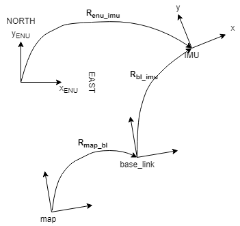
is a little weird as they are not really transformations. After writing it down on paper it looks like we could avoid using offsets in general and rely only on transformations. Below I describe my line of thought. Please let me know if you want the comment refractored in an other way. In the following I mostly refer to IMUs equiped with magnetometer and accelerometer, which I will call fully equiped. If one of the both sensors would miss, the orientations presented by IMU would have as reference some power-on initial coordinate system which we may or may not make use of, as the orientation would then be estimated only from the angular velocities which we (could) fuse directly. As I understand, fully equiped IMUs give out orientations referenced to a world fixed frame. In most scenarious these world fixed frames are ENU(x-east, y-north and z-up) or NED( x-north, y-east, z-down). Both coordinate frames are formed from a plane tangent to the Earth's surface. As shown in the photo below taken from wikipedia. We care only for the orientation of the ENU(NED) coordinate system not for its origin as we deal only with rotations. The situation is the following:
The only difficulty in all of this is how to get R_map_enu transformation which would allow as to express the measurements in map frame as: R_map_imu_meas = R_map_enu * R_enu_imu_meas. There are 2 possible solutions for that:
|

|
Sorry, not ignoring this, but I haven't had the cycles to read over it. Will get to it when I can. |
|
So first, thank you for the write-up. I haven't read back through this thread, as it's very old, and the code base will have changed a lot since this ticket was written. Are you proposing a change to the package? Is there a use case that you are trying to solve that the package doesn't support? |
See this ROS answers question for some background:
http://answers.ros.org/question/50870/what-frame-is-sensor_msgsimuorientation-relative-to/
EDIT: Just updating this to reflect the issue as I see it now. We only have a Microstrain 3DM-GX2 in house (and we're using a slightly modified driver), but the issue is that the absolute orientation is reported in a world-fixed frame, but the angular velocities and linear accelerations are reported in the sensor frame. Since the ROS IMU message type has only one
frame_id, we have to be careful defining the transform from the IMU frame to the vehicle frame. Defining a transform from the vehicle body frame to the IMU frame will work for transforming the IMU's angular velocities and linear accelerations, but may not work for the absolute orientation. But:Right now, the robot_localization will transform the IMU data - absolute orientation, angular velocity, and linear acceleration - into the frame specified by the
base_link_frameparameter. This may be sufficient for most users' needs. I'll let this issue stand while I verify a few things, but I may end up just leaving it as-is and documenting how the package behaves when it comes to IMU transformations.The text was updated successfully, but these errors were encountered: