Hardware Setup
You have a choice, you can connect to your Visonic Alarm Panel using RS232, USB or Ethernet (Wired or Wireless)
Here are some examples of how you could set up the necessary Hardware (all 3 using Ethernet)
- Hardware Setup Example (Using a USR-WIFI232-D2, USR-TCP232-E or USR-TCP232-E2)
- Hardware Setup Example (NodeMCU hardware with PowerMax Pro)
- Hardware Setup Example (Using a Wemos D1 R2 and ESPHome, including Siren Triggering)
- Hardware Setup Example (Using an M5Stack with Power Over Ethernet, using ESPHome)
The PowerMax/PowerMaster Alarm Panels provide an internal 10 pin panel connector that is labelled as the Control interface, the PC interface or the RS232 interface, this interface directly supports a TTL logic level based RS232 protocol. Visonic do not provide a specification of the RS232 protocol and, thus, the Integration uses the available protocol specification given at the domoticaforum. The binding implementation of this protocol is largely inspired by the Vera and OpenHab plugins.
Picture of the Visonic PowerMax Pro.
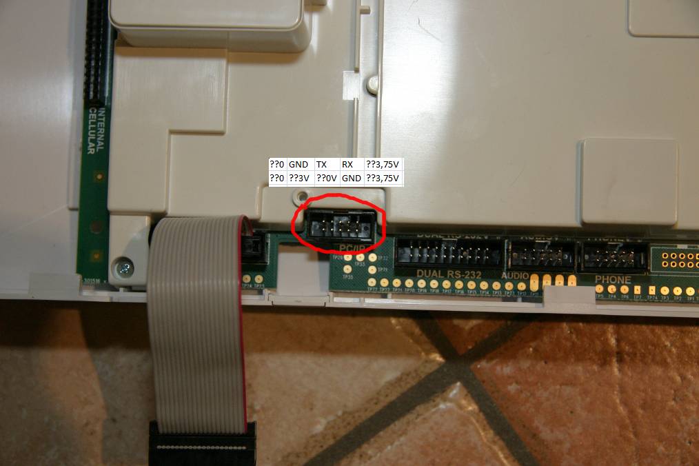
Image credit: viknet from domoticaforum.eu
Notice where the cut out is in the black plastic wall of the connector, yours may be upside down in your panel.
In your panel there may be a 14 pin connector instead of a 10 pin connector, especially in older PowerMax+ panels.
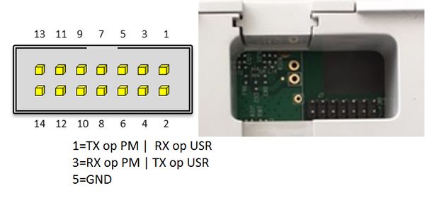
Image credit: luccie_007 from Athom forum
But I don’t have a Powermax+ panel so I would not know if this works or breaks the panel so use with caution.
Many panels also have a 20 pin connector labelled Dual RS-232, see the above PowerMax Pro image and you'll see it. I have experimented with this connector and you may be able to use the pins on this connector instead of the 10 pin connector (but you cannot use them at the same time), follow the link where I describe my experimentation.
No, please do not buy or use any of these modules. My integration mimics the functionality of these visonic modules and is used instead.
However, some panel types can have 2 active powerlink connections and it may be possible to connect both a Powerlink and have a connection to Home Assistant.
The Visonic PowerMax/Master serial interface is not installed by default but can be ordered from any PowerMax vendor (called the Visonic RS-232 Adaptor Kit). This adaptor kit makes the TTL logic levels on the panel connector in to "proper" RS232 signal levels. I have never tried this and I don't know of anyone that has. If you do it like this you're pretty much on your own.
The panel has TTL logic levels for its RS-232 connector. The Visonic RS-232 Adapter Kit converts these TTL logic levels to proper RS-232 voltage levels.
So it depends on what you buy to interface your panel with your Home Assistant, if you buy:
- An RS-232 cable to plug in to the old style DB9 RS-232 connector on a very old PC then you may need the Visonic RS-232 Adapter kit
- A USB to RS-232 cable/adapter then you need to check whether the RS-232 is TTL or proper RS-232 +/- voltage levels.
- Something like a Wemos D1 R2 or a USR-TCP232-E2 then they use TTL logic levels and you do not need the Visonic RS-232 Adapter Kit.
In summary, if the hardware that you buy to connect to your panel uses TTL logic levels for the RS-232 then you do not need the Visonic RS-232 Adapter Kit.
The panels internal RS232 interface can be connected to an RS232 9 pin "DB9" Type connection on the machine running Home Assistant. However, note that the panel interface is an RS232 connector that uses TTL logic signal levels and not "proper" RS232 voltage levels. In this case you may need the Visonic RS-232 Adapter kit.
You do not need the Visonic RS-232 Adaptor Kit if you use a USB interface with TTL RS232 logic levels. You can then connect the USB cable to a Windows PC, a Raspberry Pi, or any other Linux capable device such as some NAS devices. If you run Home Assistant on any of these devices it will likely appear to the operating system as a USB device but many of the RS232 to USB devices come with drivers to install that make it appear like a serial device in some way (e.g. on Windows it appears as a COM port)
If you use the USB option on a Raspberry Pi then these commands may be useful to you To check the settings of the serial port, assuming you have determined that /dev/ttyUSB0 is your device.
stty -F /dev/ttyUSB0 -a
To set the parameters as 9600, 8 data bits, 1 stop bit, No parity (i.e. 9600 8, N, 1) you set the parameters with:
stty -F /dev/ttyUSB0 9600 cs8 -parenb -cstopb
This is normally the default anyway but just to make sure.
If you want to connect your alarm panel to your home ethernet network then you have 3 further options. You do not need the Visonic RS-232 Adaptor Kit if you use an Ethernet interface with TTL RS232 logic levels.
This option uses a small Linux based device such as the Raspberry Pi to run the ser2net program to turn it into a network connected device.
Install ser2net on the Linux device and edit the ser2net config file like this:
10628:raw:600:/dev/serial/by-id/usb-FTDI_FT232R_USB_UART_A700eRHw-if00-port0:9600 8DATABITS NONE 1STOPBIT
Be sure to change it to the proper serial port that Linux creates (/dev/ttyUSB0 in most cases). After editing, restart the ser2net service.
Now setup the Integration in Home Assistant like the ethernet setup, using the IP address of the Raspberry Pi and 10628 as the port. Of course you can use any other port you like, but be sure to also change it in the ser2net config file and remember to restart ser2net. There are users that have this setup and can help in the forums, one main advantage is that you can use the WiFi capability of the Raspberry Pi.
Purchase and use a simple device that connects to the RS232 TTL interface inside the panel (without using the Visonic RS-232 Adapter Kit) and create an Ethernet TCP connection. Essentially this is a simple bidirectional bridge between the RS232 and your home network, it is not an intelligent device like a Raspberry Pi and is much smaller and lower power. Some devices are usable as purchased, other devices you will need to 'flash' a firmware on to them.
This allows you to connect your alarm panel to your Ethernet home network. Usually there is a webserver running on the device and you need to set it up for TCP in STA (station) mode as transparent. In the HA configuration you set the IP address and port for this device. I suggest that you avoid port numbers below 1024 as they tend to be special.
Hardware Options
- I bought this. There is a newer version out called a USR-TCP232-E2.
- There is also a WiFi version available like this that's a bit more expensive but essentially it's the same. Although you will need to also buy an aerial for it remember!
- A DOIT device here
- An iTach IP2SL and with this you can use its PoE capability to power it. If you use PoE then do not connect the power to the panel and therefore only use 3 wires to connect it.
- A NodeMCU that is flashed with esp-link firmware, it sounds complicated but it isn't really, for more details look here.
Purchase a Wemos D1 R2 (approx $10) and "flash" my ESPHome build on to it. Connect it to the RS232 TTL interface inside the panel (without using the Visonic RS-232 Adapter Kit) and create an Ethernet Connection from within Home Assistant. Essentially this is a simple bidirectional bridge between the RS232 and your home network.
This allows you to connect your alarm panel to your Ethernet home network, the Wemos ESPHome build creates a web socket. In the HA configuration you set the IP address and port for the Wemos device.
This option supports using relays connected to the wired zones inside your panel so you can trigger your siren from within Home Assistant.
Hardware Setup Example (Using a Wemos and ESPHome, including Siren Triggering)
Note that wiring for Ethernet option 3 is given in the link
You do not need to buy anything else apart from 4 wires. For some panels you can buy a connector with a cable that you can use to make it easier. I bought an "IDC 10-pin ribbon cable" for my panel but remember that the panels and connectors can be different. I then split the wires to use the 4 that I needed.
You connect it in to your Visonic alarm panel like this but this page also helps with the wiring.
I connected the 3.75v pin on the panel to the Vcc (3.3v) on my device, gnd to gnd and Tx to Rx, Rx to Tx. 4 wires and that's it. It just worked!
Some users have found that they only have 5 volts available and they need 3.3 volts and so need to use a DC supply regulator (with 2 10uF Capacitors) to generate the 3.3 volts and then they also need a logic level shifter between the 5 and 3.3 volt TTL levels.
Please understand that RS-232 is a communication protocol (logical definition) as well as a signal level specification. Traditionally, the signalling level states are -12 V (logic 1) and +12 V (logic 0). For convenience, localized connections (within a few meters) have used logic levels (TTL) for signalling.
- For the PowerMax Visonic TTL logic levels, the signalling level states appear to be 0 V (logic 0) and 5.0 V (logic 1).
- For the PowerMaster Visonic TTL logic levels, the signalling level states appear to be 0 V (logic 0) and 3.3 V (logic 1).
A quick note on Baud rates. This is relevant for all connection types as it determines the connection to the panel itself (i.e. all connection alternatives need to connect to the panel using RS232 in some way). This needs to be set in either the Ethernet/RS232 connection or the USB/RS232 connection.
The RS232 setup is to disable control flow i.e CTS/RTS, no parity and 1 stop bit.
Different panel firmware versions uses different baudrates. I believe that these are:
- 17.133 and below - baudrate is 9600
- 18.XXX and above - baudrate is 38400
However, if you have problems then try the other baudrate. Some early 18.XXX panels (e.g. Powermaster 10 v.18.040) seem to use 9600 baud for example but this isn't properly confirmed.