Components of light controller
This section describes the functionality of all the switches, jumpers and connectors of the light controller PCB.
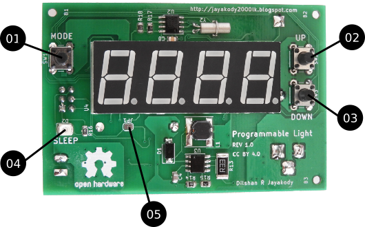
- MODE button: In the idle state, press this button to display the current system time. To open the system menu press and hold this button for a few seconds.
- UP button: In the idle state, press this button to display the light on time. In the system menu use this button to navigate to the next available option of the menu.
- DOWN button: In the idle state, press this button to display the light off time. In the system menu use this button to navigate to the previous option of the menu.
- SLEEP LED: Indicate system idle state.
- JP1 Jumper: Open this jumper to bypass the built-in LED driver and connect external driver circuitry to the controller. For more information refer the soldering and assembling section of this document.

- Battery holder: Insert CR2032 or CR2025 type battery into this holder. This battery is used to maintain the system time during power interruptions.
- 24V DC IN: Connect 24V 1A or 1.5A DC power supply into this socket.
- LED connector: Connect the 7W LED module into this connector.
- ISP header: Use this port to flash ATmega8 MCU of the light controller board. More detail about this port is available at Building and installing firmware section of this document.