CP calibration
Control pilot calibration is performed by setting the right PILOT_DOWN_THRESHOLD_X values in board.cfg.
These values are used for detection EVSE states and diode short error.
Next table descibe J1772 specification pilot states. (source)
| State | High voltage | Low voltage | Frequency | Resistance |
|---|---|---|---|---|
| A | 12 V | N/A | N/A | N/A |
| B | 9 V | - 12 V | 1 kHz | 2.74 kΩ |
| C | 6 V | - 12V | 1 kHz | 882 Ω |
| D | 3 V | - 12V | 1 kHz | 246 Ω |
| E | 0 V | 0 V | N/A | |
| F | N/A | -12 V | N/A |
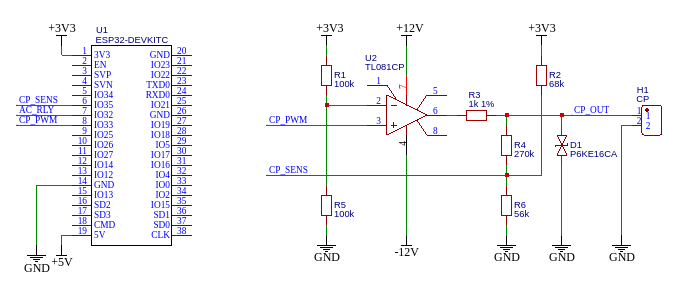
On following example circuit, sensing CP voltage is provided by voltage divider with shift (R2, R4, R6).
Wire CP_OUT is connected to the EV, CP_SENS is connected to ESP32 adc.
For this circuit there is simulation with EV side. Because state detection is performed only on high voltage, a DC power supply can be used in the simulation.
State A
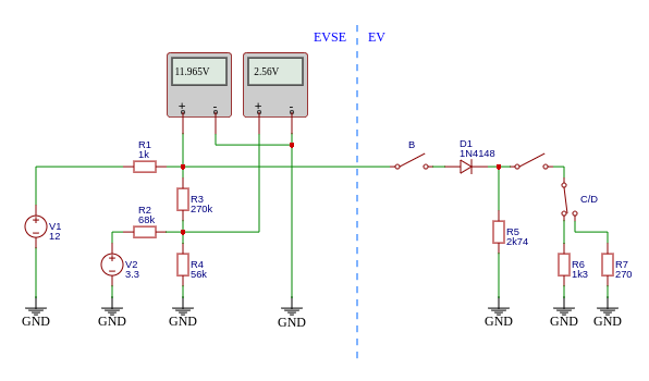
State B

State C

State D

And negative voltage
For diode short detection, just detect -6V in the lower voltage.

In next table is measured values for EV states.
| State | ADC voltage |
|---|---|
| A | 2560 mV |
| B | 2251 mV |
| C | 1948 mV |
| D | 1636 mV |
| Low voltage | 728 mV |
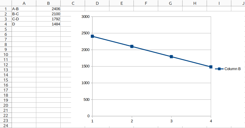
Next, calculate midpoint voltage between states, that will be used as down threshold. For state D, the value is calculated as a sequence of the difference B-C and C-D.
| State | Calculation | Down threshold |
|---|---|---|
| A-B | (2560 + 2251) / 2 | 2406 mV |
| B-C | (2251 + 1948) / 2 | 2100 mV |
| C-D | (1948 + 1636) / 2 | 1792 mV |
| D | 1792 - (2100 - 1792) | 1484 mV |
When the calculated values are displayed on the graph, they should have a linear course.
From these values board.cfg will look like this:
PILOT_DOWN_THRESHOLD_12=2406
PILOT_DOWN_THRESHOLD_9=2100
PILOT_DOWN_THRESHOLD_6=1792
PILOT_DOWN_THRESHOLD_3=1484
PILOT_DOWN_THRESHOLD_N12=728
Note When designing a new voltage divider, remember the ESP32 adc suggested range. (adc is configured for attenuation 11dB)