FloatShield
Introduction
Application programming interface
C/C++ API
MATLAB API
Simulink API
Examples
Feedback control
System identification
Detailed hardware description
Circuit design
Parts
PCB
About
Authors
The FloatShield belongs to the family of control engineering education devices for Arduino that form a part of the AutomationShield project. The basic design of FloatShield consists of a transparent vertical tube containing a ball that is floating inside due to an air current generated by a fan attached to our own-design PCB. The tube and the distance sensor are mounted by 3D printed parts. The goal is to control the position of the ball within this column measured by a distance sensor, which creates a simple single-input single-output (SISO) feedback loop. The user may also regulate power of the fan manually—using a potentiometer, the output of which is then scaled to a pulse width modulated signal (PWM).
Before you proceed, you may also want to watch a short video tutorial here.

For a better visualization the entire assembly was 3D-modeled (see the illustration below) using the CAD software CATIA V5R20 (Student Edition) and can be downloaded from here. Note that there are three parts to be 3D printed—a tube clamp, a tube lid and a sensor holder. One may also use a honeycomb tube insert to make the turbulent air flow relatively laminar. Feel free to download the ready-to-print parts. The remaining, purchased assembly parts—the fan and Arduino Uno—are downloadable from the GrabCAD database.

The basic application programming interface (API) serving the device is written in C/C++ and is integrated into the open-source AutomationShield Arduino library. This library contains hardware drivers and sample exercises for control systems engineering education. All functionality associated with the FloatShield is included in the FloatShield.h header, which contains the FloatClass class that is constructed by default as the FloatShield object. The functions specific to this shield mostly perform input/output peripheral communication.
The summary of basic functions and the illustration below should get you started quickly:
- Output (sensor):
FloatShield.sensorRead(); - Input (actuator):
FloatShield.actuatorWrite();

The following subsections describe the methods used to access the input and output of the FloatShield. Note that before you begin an experiment you must initialize the hardware by calling
FloatShield.begin();
which launches the I2C interface and starting the time of flight (TOF) sensor itself.
Although the sensor provides distance readings directly in millimeters, the outputs should be scaled to the range of 0– 100% in order to use the Serial Plotter functionality, where all outputs are scaled to the same axis. The calibration procedure is called by
FloatShield.calibrate();
finding the minimal and maximal distance readings and map these values to percentages. Later on, one may check
whether the calibration procedure was invoked or not by the wasCalibrated() method and access the minimal
and maximal distance of the ball from the sensor by executing returnMinDistance() and returnMaxDistance().
The position of the ball is read by
y=FloatShield.sensorRead();
returning the scaled distance inside the tube as a floating point value from within the range of 0–100 (%). Alternatively, sensorReadDistance() reports the distance between the sensor and the ball in millimeters, while sensorReadAltitude() gives its altitude relative to ground.
By supplying the input power u in the range of 0–100 (%) to the
FloatShield.actuatorWrite(u);
method, the user can set the power sent to the fan through the power circuitry. This method checks for constraints to avoid overflow, maps the input to 8-bit PWM integers, then sends it to the D3 pin of the Arduino.
Finally, user reference from the potentiometer is acquired by calling
r=FloatShield.referenceRead();
returning the position of the potentiometer runner as a floating point scaled to 0–100 (%).
If you cannot program in C/C++ just yet, you may want to try out the MATLAB API for the FloatShield that enables to access the hardware through the MATLAB command line and scripts. It utilizes the The MATLAB Support Package for Arduino Hardware which enables communication between the Arduino prototyping platform and the development computer.
To prevent confusion between the C/C++ and the MATLAB API, the two interfaces are as similar as possible. The MATLAB API is written in object-oriented script and the user must first create an instance from the class:
FloatShield=FloatShield;
Using MATLAB with Arduino does not compile m-script to hardware, thus invoking
HeatShield.begin();
will simply load a server code to the microcontroller, unless it is not already present. This means that the closed-loop control by the API in MATLAB is not quasi real-time, since commands are transferred through the serial link between the board and the computer and may be affected by transfer speed or operating system behavior. However, being able to use the high-level MATLAB script allows you to run live experiments under this already familiar software platform and, most importantly, to create and test more advanced control frameworks with minimal effort.
The operation of the MATLAB API is otherwise completely identical to the aforementioned Arduino version. Therefore methods such as calibrate(), sensorRead(), actuatorWrite() and referenceRead() are all implemented for the FloatShield in MATLAB.
An even more intuitive to create control loops and perform live experiments is the Simulink API for the HeatShield. It utilizes the Simulink Support Package for Arduino Hardware which supplies algorithmic units in blocks that access the hardware functionality.
The collection of the algorithmic blocks will be then available for use through the Simulink Library (see figure below) and may be combined with all the other available blocks to create feedback control applications. The Simulink API retains the naming convention and features for individual input and output blocks ('Actuator Write', 'Sensor Read' and 'Reference Read') and a comprehensive block representing the entire device is also available ('FloatShield').

In direct contrast with the way MATLAB handles Arduinos, the block scheme in Simulink is transcribed into C/C++, then compiled to machine code and uploaded to the microcontroller unit (MCU). In other words, code is run directly on the microcontroller. Simulink not only transcribes the block schemes for hardware, it also maintains the connection between the development computer and MCU. This way controllers can be fine-tuned in a live session, or data may be displayed and logged conveniently.
For a start you may want to experiment with a closed-loop control of the levitating ball's position by the proportional–integral–derivative controller (PID) algorithm.
The implementation of PID control in C/C++ is demonstrated by a worked example, which makes use of the interrupt-driven sampling subsystem of the AutomationShield library, and also its built-in input-saturated absolute-form PID method with integral windup handling by clamping. The progress of the experiments can be followed in real time through the Serial Plotter of the Arduino IDE or logged in MATLAB. Note that reference tracking is fairly accurate for the complex dynamics, while comparing inputs to the outputs exposes the nonlinearity of the system.

The same experiment can be conveniently launched from the MATLAB API as well, see the worked example. Sampling and computing the control decision is performed by the PC, while the Arduino only acts as an I/O interface. The response shown in the figure below demonstrates that a consistent closed-loop behavior is expected even when resorting to MATLAB script.

The same feedback control loop can be built even easier using the Simulink API. Shown below is the full block scheme for discrete saturated PID control of the process. You need only to select the 'FloatShield' block from the API library to implement the input/output of the hardware. Other blocks, such as the 'Discrete PID Controller', can be readily selected from the Simulink's default library.

After selecting the External mode the block scheme is transcribed into C/C++ code, which is then compiled to AVR-specific machine code and downloaded to the MCU. The application runs stand-alone on the MCU while providing basic interaction with the host PC. You may use switches, sliders and knobs to select reference levels and inspect the response live using a 'Scope'.

Note that the provided MATLAB and Simulink APIs enable to exploit full high-level mathematic power of MATLAB in order to create and test more complex estimation and control algorithms.
Input-output experiments for data gathering can be easily launched, displayed and logged using the Arduino IDE. For example, one worked C/C++ example initializes the sampling and PID control subsystems from the AutomationShield library and allows user to select whether to use PRBS (PseudoRandom Binary Sequence) or APRBS (Amplitude-modulated PRBS) signal for making small changes in input value. The example stabilizes the ball at selected position using PID control and then uses selected signal to induce small changes in the stabilized input, with the goal of monitoring system's response while avoiding saturated positions of the ball.

After you gather enough data sufficient for system identification, you may try to fit a model to the experimental response. The MATLAB API for the proposed device contains a worked example for grey-box system identification. The example offers various first-principle model formulations—a nonlinear state-space model (based on an ordinary differential equation (ODE)), a linear(ized) state-space model and a transfer function.
Once the model is specified, it takes the experimental data and searches for the unknown parameters of the specified model. First, an initial guess of the system model is created based on assumed parameter values and model structure. The unknown parameters are then found by a grey-box estimation procedure using an appropriate search method implemented in MATLAB's System Identification Toolbox. The resulting models provide a very good match to the measured input-output data (from 77% to 85%) as indicated in the figure below.

More details on the identification procedure can be found here.
The FloatShield is an open hardware product, you are free to make your own device. If you come up with improvements, please let us know so we can improve our design as well. The discussion below should help you to improvise a similar setup for experimentation on a breadboard or perforation board. You may even order a professionally made PCB by a PCB fabrication service.
The circuit schematics has been designed in the Freeware version of the DIPTrace CAD software. You may download the circuit schematics of the FloatShield from here.

The fan and the TOF sensor are only represented by their connectors, while we assume that 12 V external power is drawn through the VIN pin of the Arduino (a).
The fan is powered by an N-channel MOSFET C1 (l), and driven by the D3 PWM capable microcontroller pin through an 1 kΩ current limiting resistor R1 (m). Floating states are handled by a 10 kΩ pull-down resistor R2 (n), while a diode D1 (o) ensures back electromotive-force (EMF) protection. A connector (p) finally leads to the fan terminals. Since the fan requires 12 V and more current than the USB-powered Arduino can handle, a separate wall adapter power supply is required to operate the device.
The TOF sensor is integrated to a convenient open-source breakout board, thus it can be effortlessly connected (q) to the I2C bus of the Arduino (SDA,SCL).
Finally, the potentiometer POT1 (r) runner is attached to the A0 ADC capable pin of the board.
To make a FloatShield either on a PCB or on a breadboard you will need the following parts or their similar equivalents:
| Part | Name | Type/Value/Note | PCS |
|---|---|---|---|
| (b) | PCB | FR4, 2 layer, 1.6mm thick | 1 |
| (c) | Fan | Axial, 12 V, 40X40 mm, 24.0 CFM; e.g. Sunon PMD1204PQB1 | 1 |
| (d) | Tube clamp | 3D printed, 16g filament, print time 2:24h | 1 |
| (e) | Tube | Clear, Ø35.5 mm, wall approx. 0.6mm, 0.4m; e.g. no. 113816 | 0.4m |
| (f) | Ball | Cork, Ø30 mm; e.g. no. 108269 | 1 |
| (g) | Tube flange | 3D printed, 5.8g filament, print time 57min | 1 |
| (h) | Sensor holder | 3D printed, 4g filament, print time 43min | 1 |
| (i) | Sensor | ST Microelectronics VL5310X TOF sensor on a breakout board | 1 |
| (j) | Wire | 1m, 4 lead, 0.15mm2, multi-conductor ribbon; e.g. VFL 4x0,14 | 1 |
| (k) | Cable shaft | U-shape, 8x330mm, ASA polymer; e.g. 11796 | 1 |
| (l), C1 | MOSFET | IRF520, TO-220AB, e.g. IRF520NPBF | 1 |
| (m), R1 | Resistor | 1kΩ, 2.5x6.8mm, THT | 1 |
| (n), R2 | Resistor | 10kΩ, 2.5x6.8mm, THT | 1 |
| (o), D1 | Diode | 1N4001, e.g 1N4001-DCO | 1 |
| (p) | Connector (fan) | 2x1 pin, 0.1" pitch; e.g. TE Connectivity 280358 | 1 |
| (p), J2 | Jumper (fan) | 2x1 pin, 0.1" pitch; e.g. TE Connectivity 280370-2 | 1 |
| (q) | Connector (sensor) | 6x1 pin, 0.1" pitch; e.g. TE Connectivity 280360 | 1 |
| (q), J1 | Jumper (sensor) | 6x1 pin, 0.1" pitch; e.g. TE Connectivity 280372-2 | 1 |
| (q),(p) | Connector pins | e.g. TE Connectivity 182206-2 | 14 |
| (r) | Turning knob | 5x18.7mm; e.g. ACP 14187-NE | 1 |
| (r), POT1 | Potentiometer | 10kΩ | 1 |
| (s) | Header | 10x1 pin, female, long, stackable, 0.1" pitch | 1 |
| (s) | Header | 8x1 pin, female, long, stackable, 0.1" pitch | 2 |
| (s) | Header | 6x1 pin, female, long, stackable, 0.1" pitch | 1 |
| - | Bolts | DIN 912 M3x40 | 4 |
| - | Bolts | DIN 912 M3x16 | 2 |
| - | Nuts | DIN 934 M3 | 6 |
| - | Screws | DIN 7981F 2.9x9.5 | 2 |
| - | Washers | DIN125 A 3.2x7x0.5 Polyamide washers | 4 |
| - | Standoffs | TFM-M3/10 | 4 |
Note that the total cost of the above components and thus of the entire FloatShield is no more than $30 excluding labor and postage.
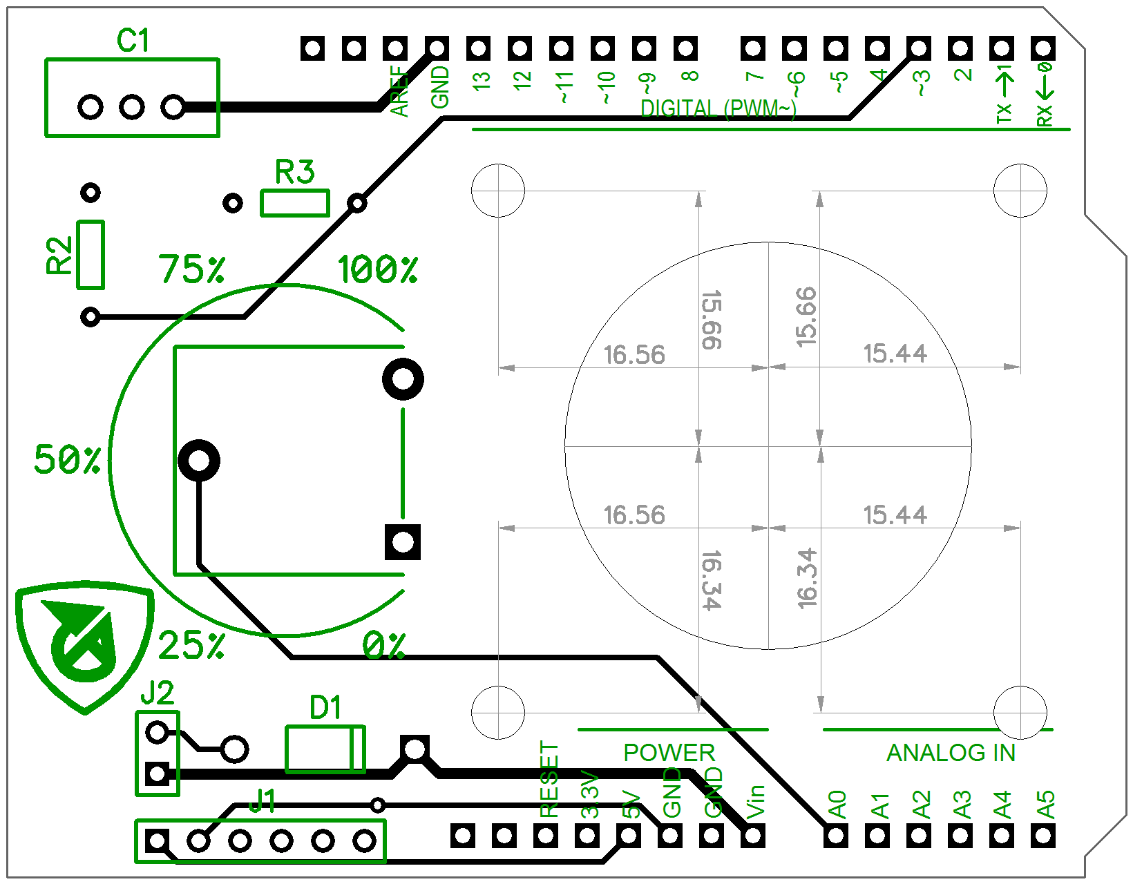
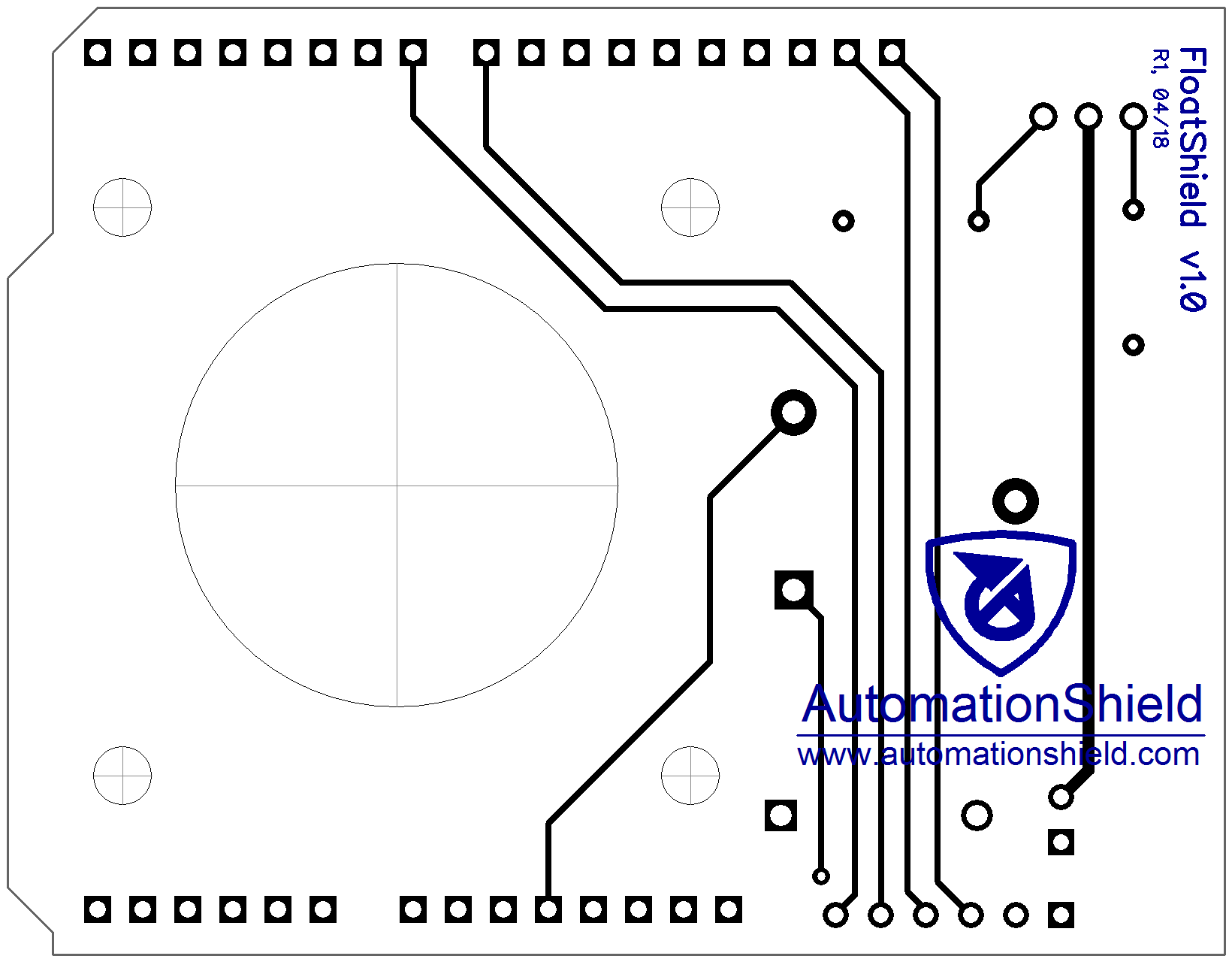
The printed circuit board has been designed in the Freeware version of the DIPTrace CAD software. The PCB is two-layer and fits within the customary 100 x 100 mm limit of most board manufacturers. The DIPTrace PCB layout and circuit schematics can be downloaded here and here, respectively, while the ready-to-manufacture Gerber files with the NC drilling instructions are available from here.
The assembled shield is fixed mechanically and electrically to the Arduino board through stackable header pins. The location of the components is also illustrated in the PCB layout below. The axial fan is mounted to the board on standoffs and a hole cut at the manufacturing stage of the PCB increases the air intake capacity.
This shield was designed and created as a term project at the Institute of Automation, Measurement and Applied Informatics. The Institute belongs to the Faculty of Mechanical Engineering (FME), Slovak University of Technology in Bratislava in 2017/2018.
- 3D-model design: Marcel Vdoleček
- Hardware design: Peter Šálka, Miloš Podbielančík, Dávid Šroba, Martin Lučan
- Software design: Gábor Penzinger, Jakub Kulhánek
- Wiki documentation: Martin Gulan, Erik Mikuláš and Gergely Takács

Takács et al., 2018-2023. The hardware design, software and manual featured in this repository is licensed under a Attribution-NonCommercial-NoDerivatives 4.0 International (CC BY-NC-ND 4.0). Please consider citing our work in your publication.
