PressureShield
Introduction
Application programming interface
C/C++ API
Examples
Feedback control
Detailed hardware description
Circuit design
Parts
PCB
About
Authors
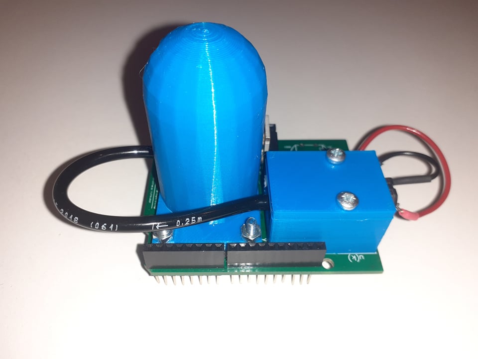
The PressureShield belongs to the family of control engineering education devices for Arduino that form a part of the AutomationShield project. The basic design of PressureShield consists of a vessel with integrated pressure sensor that is mapping pressure in the vessel and a pump. The goal is to obtain and keep the required value of pressure in the vessel despite its leakage. The value can be set by the user using the potenciometer. The power of the pump can be varied by applying a pulse width modulated (PWM) signal to it, thus manipulating airflow. The pump is an actuator and with the sensor it creates a simple single-input single-output (SISO) feedback loop that can be used in control engineering experiments.
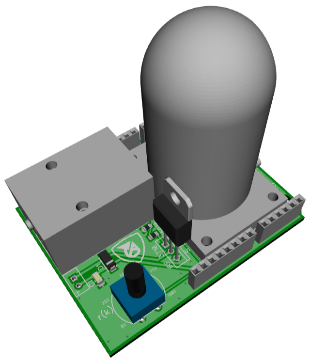
For a better visualization the entire assembly was 3D-modeled (see the illustration below) using the DIPTrace CAD software and can be downloaded from here. Note that there are four parts to be 3D printed—a pump holder, a pump cap, a vessel and a backplate. One may also use a spiral fill structure and support parts for hollow objects. Feel free to download the parts.
The basic application programming interface (API) serving the device is written in C/C++ and is integrated into the open-source AutomationShield Arduino library. This library contains hardware drivers and sample exercises for control systems engineering education. All functionality associated with the PressureShield is included in the PressureShield.h header, which contains the PressureClass class that is constructed by default as the PressureShield object. The functions specific to this shield mostly perform input/output peripheral communication.
The summary of basic functions should get you started quickly:
- Output (sensor):
PressureShield.sensorRead(); - Input (actuator):
PressureShield.actuatorWrite();
The following subsections describe the methods used to access the input and output of the PressureShield. Note that before you begin an experiment you must initialize the hardware by calling
PressureShield.begin();
which launches the I2C interface and starting the pressure sensor itself.
Although the sensor provides pressure readings directly in pascals, the outputs should be scaled to the range of 0– 100% in order to use the Serial Plotter functionality, where all outputs are scaled to the same axis. The calibration procedure is called by
PressureShield.calibrate();
finding the minimal pressure readings. The max pressure value is fixed to 106000Pa due to component protection. Then map these values to percentages.
The actual pressure in the vessel is read by
y=PressureShield.sensorRead();
returning the scaled pressure inside the vessel as a floating point value from within the range of 0–100 (%).
By supplying the input u in the range of 0–100 (%) to the
PressureShield.actuatorWrite(u);
method, the user can set the power sent to the pump through the power circuitry. This method checks for constraints to avoid overflow, maps the input to 8-bit PWM integers, then sends it to the D11 pin of the Arduino.
Finally, user reference from the potentiometer is acquired by calling
r=PressureShield.referenceRead();
returning the position of the potentiometer runner as a floating point scaled to 0–100 (%).
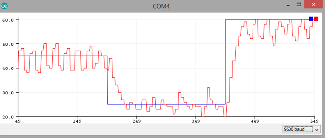
For a start you may want to experiment with a closed-loop control of the pressure in the vessel by the proportional–integral–derivative controller (PID) algorithm.
The implementation of PID control in C/C++ is demonstrated by a worked example, which makes use of the interrupt-driven sampling subsystem of the AutomationShield library, and also its built-in input-saturated absolute-form PID method with integral windup handling by clamping. The progress of the experiments can be followed in real time through the Serial Plotter of the Arduino IDE.
The PressureShield is an open hardware product, you are free to make your own device. If you come up with improvements, please let us know so we can improve our design as well. The discussion below should help you to improvise a similar setup for experimentation on a breadboard or perforation board. You may even order a professionally made PCB by a PCB fabrication service.
The circuit schematics has been designed in the Freeware version of the DIPTrace CAD software. You may download the circuit schematics of the PressureShield from here.
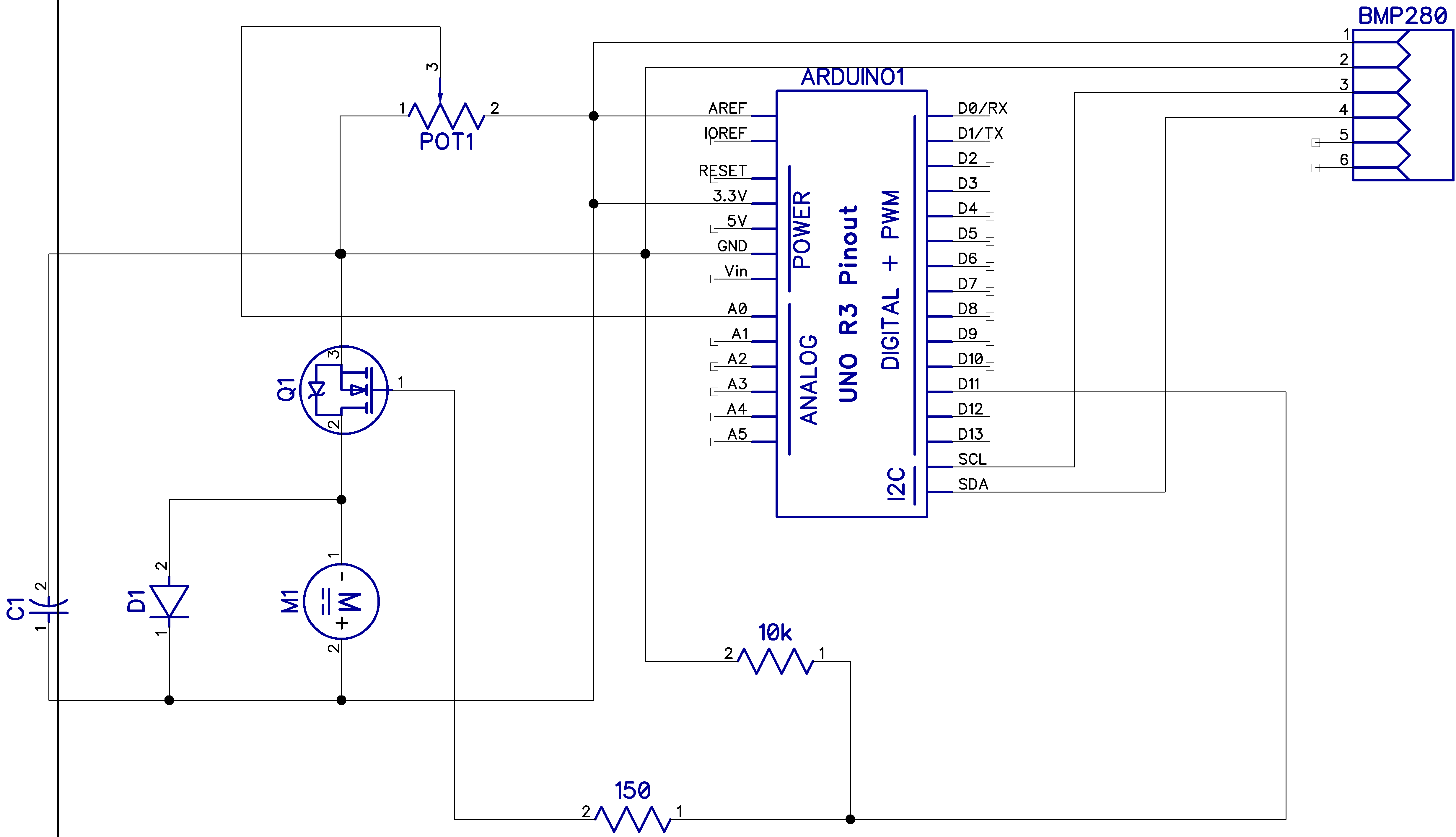
The pressure sensor is only represented by its connectors, which are connected to I2C communication pins of the Arduino and 3,3V power source and GND.
The pump is powered by an N-channel MOSFET **Q1 **, and driven by the D11 PWM capable microcontroller pin through an 150 Ω current limiting resistor **R1 **. Floating states are handled by a 10 kΩ pull-down resistor **R2 **. A diode **D1 ** protects the microcontroller from reverse current caused by possible back electromotive force (EMF), while transient effects on the servo supply are filtered by a capacitor .
Finally, the potentiometer **POT1 ** runner is attached to the A0 ADC capable pin of the board, that allows the user to program this input for any purpose, such as providing reference to the feedback control loop.
To make a PressureShield either on a PCB or on a breadboard you will need the following parts or their similar equivalents:
| Part | Name | Type/Value/Note | PCS |
|---|---|---|---|
| (b) | PCB | FR4, 2 layer, 1.6mm thick | 1 |
| (c) | Pump | Miniature vacuum pump: 3V, 160mA, 30kPa | 1 |
| (d) | Pressure Sensor | BMP280, I2C, pressure sensore module | 1 |
| (e) | N-Mosfet | IRF 3710, TO-220, e.g. IRF3710PBF | 1 |
| (f) | Capacitor | Tantalum, SMD, 10uF | 1 |
| (g) | Diode | DO-214AC(SMA) | 1 |
| (h) | Resistor | SMD 10kΩ | 1 |
| (i) | Resistor | SMD 150kΩ | 1 |
| (j) | Potentiometer | 1 | |
| (k) | Potentiometer | 10kΩ | 1 |
| (s) | Header | 10x1 pin, female, long, stackable, 0.1" pitch | 1 |
| (s) | Header | 8x1 pin, female, long, stackable, 0.1" pitch | 2 |
| (s) | Header | 6x1 pin, female, long, stackable, 0.1" pitch | 1 |
| (l) | Vessel | 3D printed | 1 |
| (m) | Backplate | 3D printed | 1 |
| (n) | Pump holder | 3D printed | 1 |
| (o) | Pump cap | 3D printed | 1 |
| (p) | Screw | M3x16 | 4 |
| (q) | Nut | M3 | 4 |
| (r) | Self-tapping screw | M3x8 | 4 |
| (t) | Tube | 4x110mm | 1 |
| (u) | Cable | 70mm | 2 |
| (v) | Gasket | 1 |
Note that the total cost of the above components and thus of the entire PressureShield is no more than $30 excluding labor and postage.
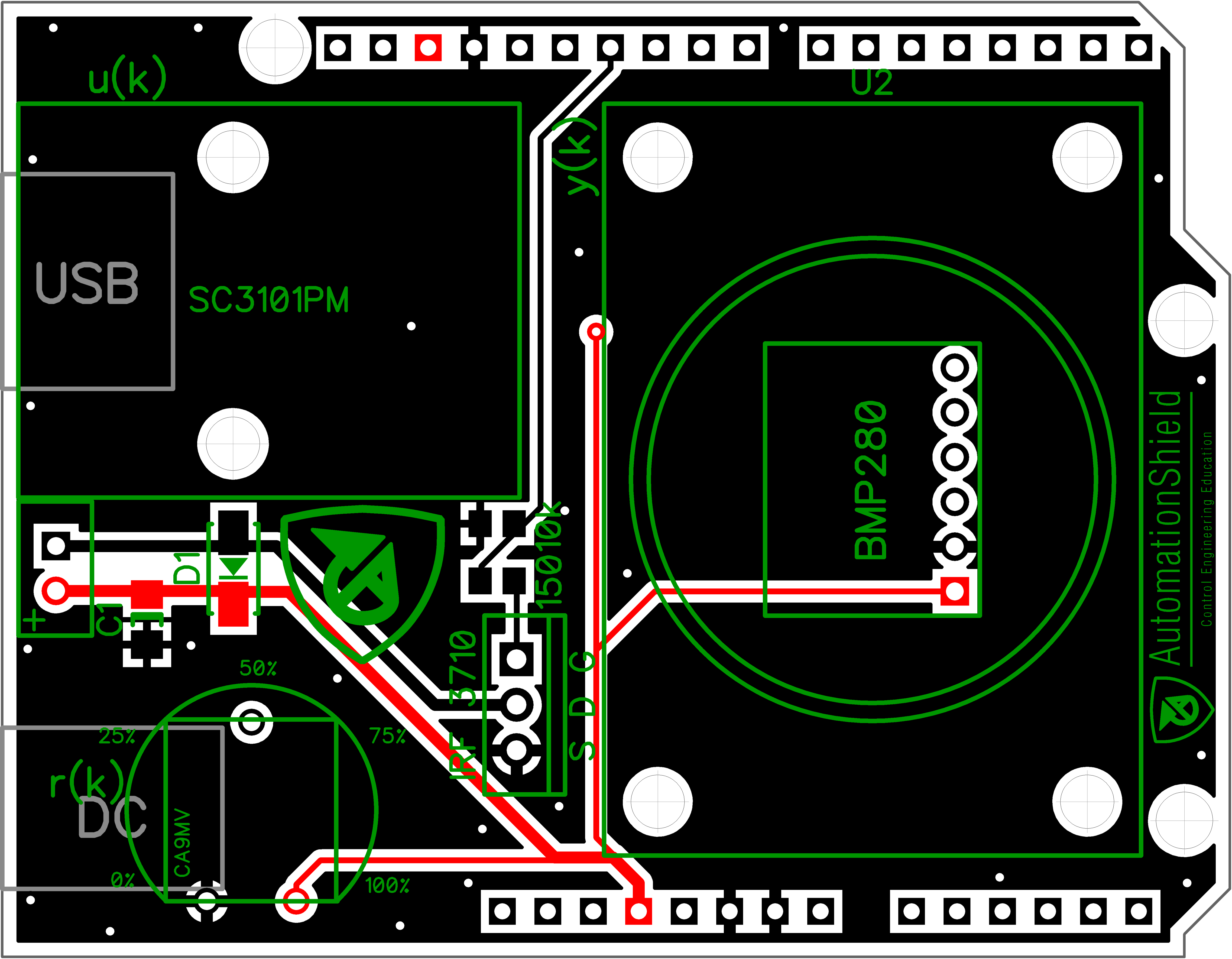
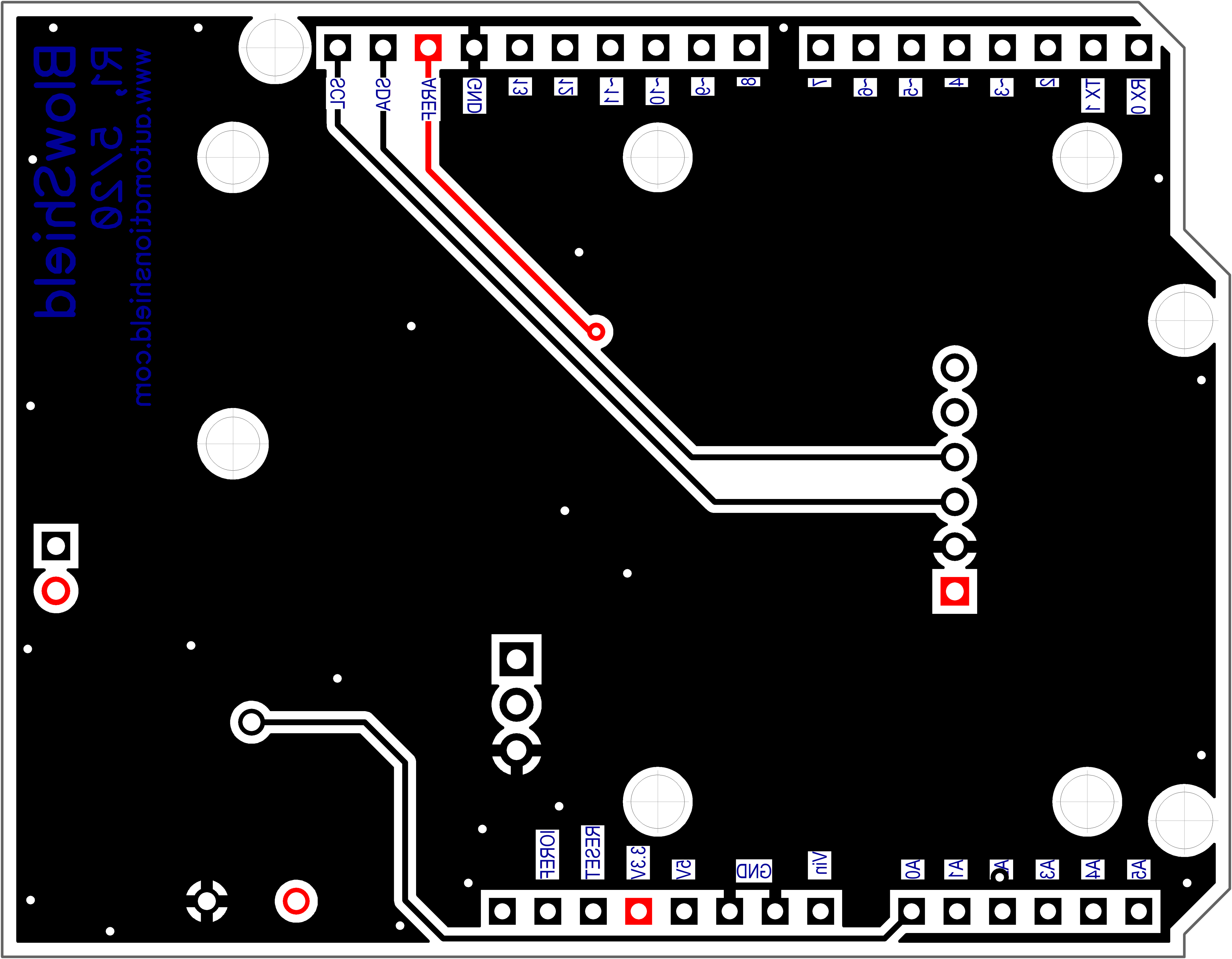
The printed circuit board has been designed in the Freeware version of the DIPTrace CAD software. The PCB is two-layer and fits within the customary 100 x 100 mm limit of most board manufacturers. The DIPTrace PCB layout and circuit schematics can be downloaded here and here, respectively, while the ready-to-manufacture Gerber files with the NC drilling instructions are available from here.
The assembled shield is fixed mechanically and electrically to the Arduino board through stackable header pins. The location of the each component is illustrated in the PCB layout below. The pump is mounted to the board on holder and covered by cap. The sensor is situated in the vessel. Backplate under the PCB board is also used for reinforcement the structure. Due to small space between the vessel and the pump, the suction pipe of the pump must be shortened (at least half of the original length). The connection of the tube with the vessel needs to be sealed up, one may use superglue or epoxy glue.
This shield was designed and created as a term project at the Institute of Automation, Measurement and Applied Informatics. The Institute belongs to the Faculty of Mechanical Engineering (FME), Slovak University of Technology in Bratislava in 2019/2020.
- 3D-model design: Tomáš Tužinský
- Hardware design: Martin Staroň, Martin Vríčan, Lukáš Kavoň
- Software design: Anna Vargová, Eva Vargová
- Wiki documentation: Vladimír Kmeť, Erik Mikuláš and Gergely Takács
- Postman: Matúš Ľeginus
- Technical support: Radoslav Gago

Takács et al., 2018-2023. The hardware design, software and manual featured in this repository is licensed under a Attribution-NonCommercial-NoDerivatives 4.0 International (CC BY-NC-ND 4.0). Please consider citing our work in your publication.
