This is a work in progress:
- Tested with RS-BA1 V1 & V2
- Switches work and LED's light as they should.
- Encoder sensitivity can be changed by adjusting a define at the top of the file.
- The dial sensitivity on RS-BA1 software has minimal impact (if any). As far as I can see the slider does not send anything to the RC-28.
Copyright GI1MIC (2021)
** For non-commercial use only**
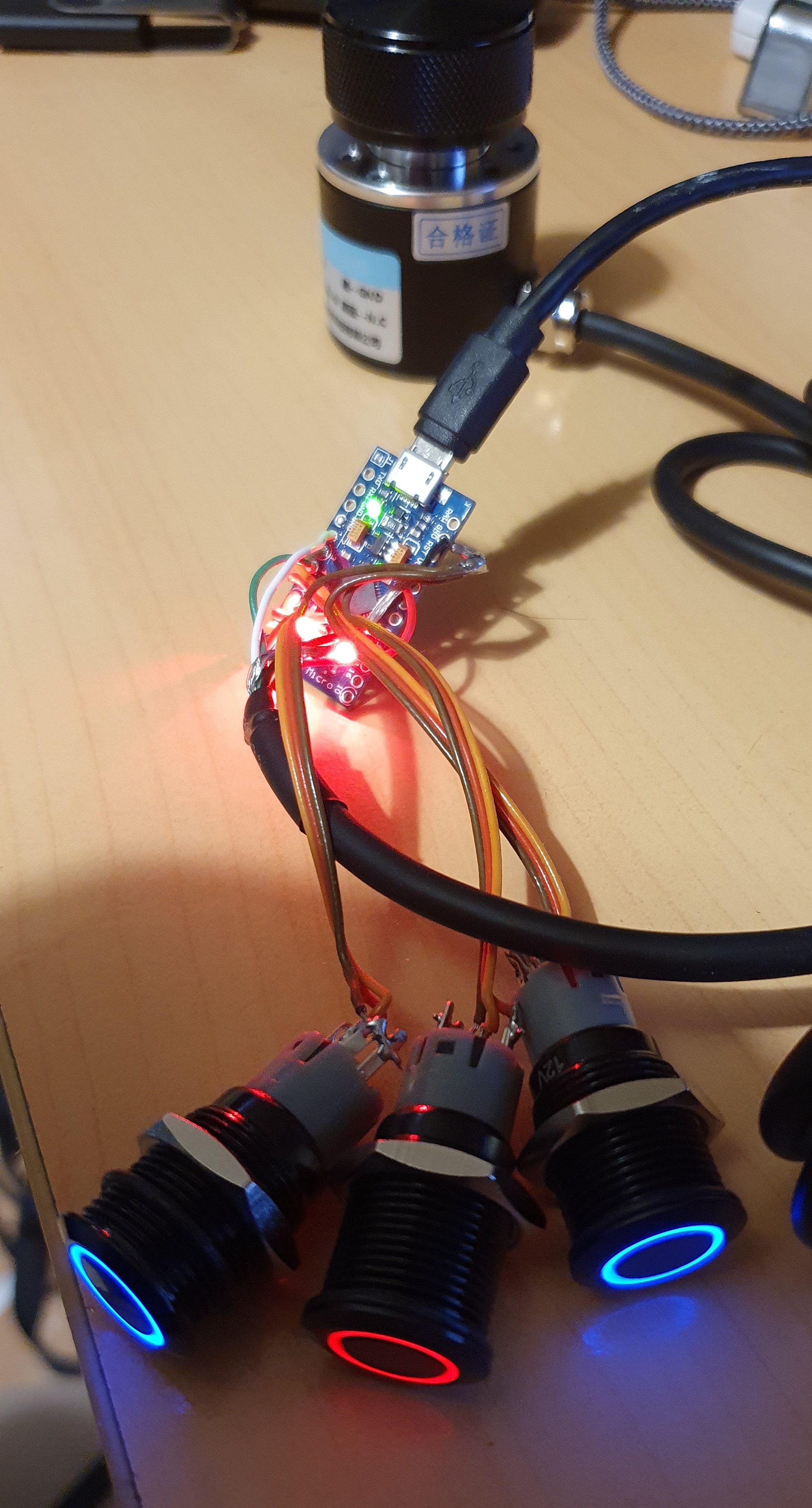
- 3 x Arduino Pro Mini (32u4, 16Mhz, 5V version) (~£20 for three - search Amazon/eBay for 32u4 arduino)
- 3 x momentary push-to-make buttons to act as TX, F1 and F2 (From £6 each - search Amazon/eBay for HALJIA 16mm Red Ring Led Metal Momentary Push Button. Inc's LEDs) Note, these buttons are fine for the functions but require to much travel to make a good TX switch)
- 3 x LED's to show TX, F1, F2 status
- 1 x Optical encoder (5V-24V 600P/R with 6mm shaft) (From £9 - search Amazon/eBay for 600p/r encoder)
- 1 x ~30mm knob for 6mm shaft (preferably the machined aluminum type for mass) (From £8 - try searching Amazon/eBay for aluminium tuning knob 30mm)
- 1 x enclosure of choice
This project requires modification of the standard Arduino USB configuration files. For this reason it is recommend you setup a standalone version of the Arduino IDE. This will ensure you do not interfere with any other Arduino projects you may have.
To do this under Windows download the ZIP file version of the Arduino IDE and extract it into a directory. Within this directory create another folder called "portable". Double click on the arduino.exe file you just extracted and it will create a directory structure under the portable directory you just created.
At this point you now have a standalone (portable) version of the Arduino IDE where all library files and sketches are held in the portable directory.
Next install the "HID-Project" library by NicoHood (https://github.com/NicoHood/HID) and the "Rotaryencoder" library by mathertel (https://github.com/mathertel/RotaryEncoder). Both are available via the standard Arduino library manager.
Once installed they should appear as directories under portable\sketchbook\libraries called HID-Project and RotaryEncoder.
Now download the provided source file and place it under the portable folder in "portable\sketchbook\rc28_emulator". At this point, if you select "Arduino Leonardo" as the target platform you should be able to compile the code as a quick test.
NOTE: I have included the modified files for Version 1.8.13 of the Arduino IDE for reference. If you are using the same version you can just replace the installed version with the provided ones. Otherwise please edit the versions that came with you IDE based on the following.
If all is well exit the IDE and insert the following to hardware\arduino\avr\boards.txt (just after the Leonardo section) to create a "new" board variation that reports the necessary device name and USB VID/PID
  //##############################################################
  leonardo.name=Arduino Leonardo - RC-28
  leonardo.vid.0=0x2341
  leonardo.pid.0=0x0036
  leonardo.vid.1=0x2341
  leonardo.pid.1=0x8036
  leonardo.vid.2=0x2A03
  leonardo.pid.2=0x0036
  leonardo.vid.3=0x2A03
  leonardo.pid.3=0x8036

  leonardo.upload.tool=avrdude
  leonardo.upload.protocol=avr109
  leonardo.upload.maximum_size=28672
  leonardo.upload.maximum_data_size=2560
  leonardo.upload.speed=57600
  leonardo.upload.disable_flushing=true
  leonardo.upload.use_1200bps_touch=true
  leonardo.upload.wait_for_upload_port=true

  leonardo.bootloader.tool=avrdude
  leonardo.bootloader.low_fuses=0xff
  leonardo.bootloader.high_fuses=0xd8
  leonardo.bootloader.extended_fuses=0xcb
  leonardo.bootloader.file=caterina/Caterina-Leonardo.hex
  leonardo.bootloader.unlock_bits=0x3F
  leonardo.bootloader.lock_bits=0x2F

  leonardo.build.mcu=atmega32u4
  leonardo.build.f_cpu=16000000L
  leonardo.build.vid=0x0C26
  leonardo.build.pid=0x001E
  leonardo.build.usb_product="Icom RC-28 REMOTE ENCODER"
  leonardo.build.board=AVR_LEONARDO
  leonardo.build.core=arduino
  leonardo.build.variant=leonardo
  leonardo.build.extra_flags={build.usb_flags}
Now modify hardware\arduino\avr\cores\arduino\USBcore.cpp and change the #if section at the top of the file to match the following:
  #if USB_VID == 0x2341
  #  if defined(USB_MANUFACTURER)
  #    undef USB_MANUFACTURER
  #  endif
  #  define USB_MANUFACTURER "Arduino LLC"
  #elif USB_VID == 0x1b4f
  #  if defined(USB_MANUFACTURER)
  #    undef USB_MANUFACTURER
  #  endif
  #  define USB_MANUFACTURER "SparkFun"
  #elif USB_VID == 0x0C26
  #  if defined(USB_MANUFACTURER)
  #    undef USB_MANUFACTURER
  #  endif
  #  define USB_MANUFACTURER "Icom Inc."
  #elif !defined(USB_MANUFACTURER)
  // Fall through to unknown if no manufacturer name was provided in a macro
  #  define USB_MANUFACTURER "Unknown"
  #endif
further down the file (around line 536 change)
return USB_SendStringDescriptor((uint8_t*)name, strlen(name), 0);
to
return USB_SendStringDescriptor((uint8_t*)"RC-28 0102001", strlen("RC-28 0102001"), 0);
Going by the manual the serial number should be in the format "02XXXXX" but I do not think it is actually checked or used other than for display.
If you restart the Arduino IDE you should now have a new custom board type called "Arduino Leonardo - RC-28". Select this and upload the result to a standard Adruino Pro Micro.

You can always select "Arduino Leonardo - ETH" as a target if you want to re-use the board on another project.
-
VCC Encoder red
-
PIN2 Encoder White (This pin must be used for encoder interrupts)
-
PIN3 Encoder Green (This pin must be used for encoder interrupts)
-
GND Encoder Black
-
GND Encoder Shield
-
PIN8 F1 Button
-
PIN9 F1 LED
-
PIN4 F2 Button
-
PIN5 F2 LED
-
PIN6 TX Button
-
PIN7 TX LED
The other side of the buttons and LED's go to GND
Simply plug it into a host PC running the RS-BA1 software and it will be detected just like a real RC-28.
The arduino will also appear as a serial COM port on your machine. This means you can use standard "Serial.print" commands within the code to debug if you want.
- This is not a true emulation of the RC-28 since the arduino is configured to emulate both a HID and USB serial device simultaneously. Also the RC-28 sends it reports via USB_Interrupt messages but straight HID messages seem to work just fine which is what this code generates.
- Not sure I have the response bit patterns 100% correct but without a RC-28 all I can do is test against the RS-BA1 software.
- This code has not been tests against with IC-7610 but if you try it please let me know what happens.
- A big thank you Philippe for his help in this project. Without his help I would never have got this to work.
- The real RC-28 uses a PIC18F14K50 as the processor. Microchip have some application notes and sample code for USB usage so it would probably not be that big a task to port this code to that processor.
- I think ICOM use an 128bit AES key for encrypting their firmware updates (at least on newer updates). The PIC processor supports AES in hardware. For that reason it would probably be a waste of time to try modifying my code to dump the PIC firmware from one of their update programs without the AES key.
- You should be able to use a Magnetic Encoder instead of an optical encoder. It looks like the magnetic encoders only have 100p/r resolution but that should be fine. Simply modify the define at the top of the code to increase the sensitivity to compensate.