Spindle sync
** PRELIMINARY **
Spindle synced motion requires an encoder with two outputs, one generating one pulse per revolution (index) and one generating more than one per revolution (pulse).
$32 Mode of operation. This has to be set to 2 - lathe mode.
$38 Spindle PPR. Set to number of pulses per revolution (PPR) from the encoder.
$90 Spindle P gain. Control loop P gain. Typically set to 1 or more at the start of tuning.
$91 Spindle I gain. Control loop I gain. Typically set to a small value, start with 0 or 0.005.
$92 Spindle D gain. Control loop D gain. Typically set to 0.
$94 Spindle max error.
$95 Spindle max I error.
$341 Spindle at speed tolerance. Percent allowed deviation from progammed speed that is acceptable. If set to 0 ensure that the spindle has spun up before commanding spindle synced moves, e.g. by a G4 command.
The position of the controlled point (tooltip) is constantly adjusted to keep it in sync with the angular position of the spindle. This is done via a PID control loop which has to be "tuned" to match the dynamic properties of the machine.
ioSender has a PID tuning tab for visualizing the system behaviour which greatly simplifies this task.
This is autmatically shown if PID logging is enabled in the controller.
Execute a G33 command to fill the log with data and then fetch it in the tab to see how close the actual position matches the programmed position over the move.
Adjust the PID parameters so that the actual position catches up as quicly as possible with the programmed position and then do not oscillate (ring) by any significant amount afterwards.
A step signal is often used to see how the feedback loop behaves. Luckily one is inherent in any spindle synced move as the feedback loop cannot be active during the acceleration phase as this will force the acceleration to above the specified Z-axis limit. Due to this the programmed position is always out of sync with the actual position when the cruising phase starts.
Low P gain, slow correction with a little overshoot:

Good P gain, quick correction without overshoot:
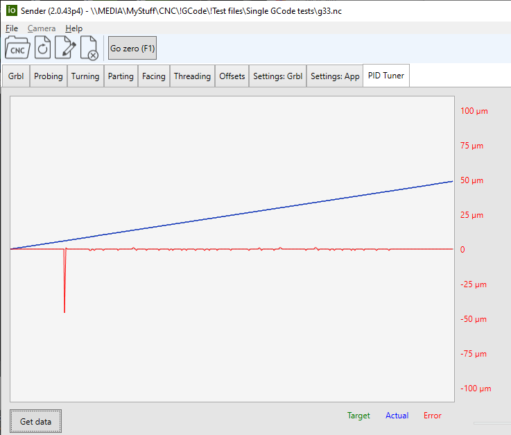
Too high P gain, quick correction but large overshoot and unstable with ringing:

Test program used to generate the plots above:
m3s200
g0x2
g0z2
g1x0f50
g33z-15k1.5
g0x2
g0z2
m30
Since spindle synced motion requires encoder input providing spindle RPM I decided to make an app to run the spindle through the configured range.
This plots the programmed RPM vs. the actual RPM and can save the data in a format usable by the
spindle linearizer code made available by the lead legacy Grbl developer.
This can be used to generate data for settings $66 - $69, available if grblHAL is built with the spindle linearization option.
The app is available for download from the Io Engineering site (Windows only).
An example from after tuning my 0-10V controlled VFD by just changing the $35 and $36 settings:

2024-02-25