Wireless time measurement with two buzzer buttons, which also work as standalone.
The GUI is controlled by the three buttons, called previous, next, and confirm. Generally speaking, while navigating you use the previous button to go to the previous element, the next button to go to the next element, and press the confirm button, to leave or enter a menu.
To change a value, you first need to navigate to the corresponding element. Then you press the confirm button to start changing the value. Use the previous button to lower the value, and use the next button to increase it. When done editing the value, press the confirm button again to confirm your input.
While being in either the stopwatch or timer mode, pressing the buzzer button will start the time, and pressing the buzzer button again will stop it. You can also cancel out by pressing the confirm button on the cancel element. After canceling no result is shown.
When in the same wireless channel and same mode, pressing either of the buzzer buttons will stop the time.
Detailed information about the usage and limits can be found in the wiki.
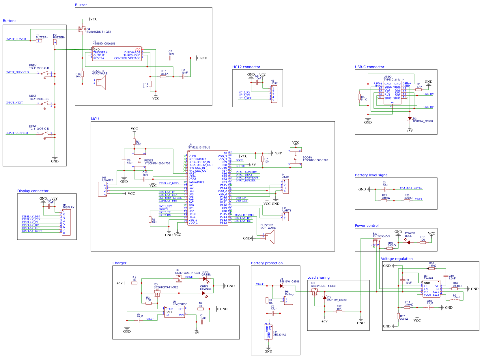
The design is based around the STM32L151CBU6 microcontroller, which drives an HC12 long-range wireless communication module and a Waveshare 2.13-inch black and white e-ink display. The board is powered via a 1000mAh LiPo battery which is charged via USB-C. The data lines of the USB-C port are connected to the MCU to provide expandability as well as an exposed additional UART connection on the PCB itself.
Even though this project uses an HC12 module, I highly recommend replacing it. Not only is it practically impossible to find genuine modules which can deliver on the promised range, but more importantly requires the used frequency of 433 MHz a license in large parts of the world. A promising alternative could be the RYLR998 LoRa module by REYAX. It operates in a licenses free frequency range, should achieve an even higher range, and has a small size. As it gets also controlled via AT-commands like the HC12, the changes required should be small.
JTAG and UART with buttons to select the boot mode are also exposed for uploading and debugging firmware.
The base of the casing is this emergency off buzzer, all other parts are 3D-printed. One of the wider sides is then cut open to place the front panel, which also secures the display. The other components are on a mounting system, which is screwed to the bottom of the buzzer.
Due to the limited size of the chosen casing, a custom PCB is used. The schematics are created with EasyEDA, as their integration with LCSC Electronics made the design and ordering process a lot simpler for me. As this is a cloud-based solution, you can open the schematics directly.
The production files are also directly included in this repository nevertheless.
This project uses an Arduino CMake toolchain, but it is still possible to compile it within the Arduino IDE. The only limitations are as follows:
- The
SportBuzzer.inofile needs to be a file without any code in it to keep it compatible with both the Arduino IDE and the CMake toolchain. The only purpose of this file is to make it possible to open the project in the Arduino IDE. - Due to the project size, it is necessary to split the project into multiple source files, which are organized in
directories. The starting point of those directories needs to be
src/, so the Arduino IDE picks it up. Still, the Arduino IDE won't show the directories and the containing files in the Editor.
The basic concepts of the code are as followed:
- Abstract the hardware as much as needed, so you are able to change it without needing to change stuff all over the code base.
- The main loop (
void loop()to be more specific) handles background tasks. Background tasks include checking the battery level and the connection status. The main loop updates the foreground task (calledGUITask) also, providing information about the hardware state, which it has already queried. To keep the displayed device state up to date, it may redraw the GUI arbitrarily. - A GUITask handles everything related to its options, and time measurements. When done updating, it returns itself to keep alive, or a new GUITask to exit. After exiting, its state gets destroyed.
- To get accurate times without being limited by the refresh rate of the display, the buzzer is handled completely via interrupts. Implementations of GUITask rely on the time when the buzzer was pressed to detect if it was pressed.
A full documentation of the code can be found in the wiki.
Support from the Arduino IDE for the STM32-based microcontroller is added via the stm32duino project. The correct settings for the custom PCB are as follows:
- Board: "Generic STM32L1 series"
- Board part number: "GenericL151CBUx"
Remember to also choose the appropriate upload method.