Landslide generated wave (2D)
This example shows the gravity-driven slide of a block along a slope into water and the generation of waves. It demonstrates how to use @iSALE@ for landslide simulations (here: in two dimensions).
By turning off the cylindrical projection in 2D,
CYL Cylind. geometry : 0.0D0
the sliding block is represented by a triangular shaped object. To model a sand-like behavior of the sliding body, a Tillotson equation of state with parameters for granite is used and a Drucker-Prager strength model is applied with low cohesion (10 KPa) and a coefficient of internal friction of 0.4. The slope has an angle of 45° and is composed of a strong material. For this purpose a Von Mises yield criterion is used. The thermodynamic behavior is calculated by a Tillotson equation of state for granite, too.
Go to the relevant example directory
cd /share/examples/landslide
Run iSALE2D. 8The simulation will take a day or even longer*, so this should be run in the background.
./iSALE2D &
Now it is time for a closer look how the geometric bodies, such as the slope and the sliding block, are defined in @iSALE@. First, we need to tell iSALE that we want to perform landslide simulations. This is done by the line
S_TYPE Setup type : LANDSLIDE
in the input-file (asteroid.inp).
By doing so, iSALE will switch from the default setup-procedure to a separate setup-routine specifically designed for landslide-scenarios. This routine requires additional parameters which need to be provided with the input-file (asteroid.inp):
| abbreviation | Description | type | optional? | default value (if optional) |
|---|---|---|---|---|
| SLOPE_LAY | reference layer for slope | integer | yes | 1 (first layer) |
| SLOPE_H | slope height | integer | no | |
| SLOPE_ANG | slope angle | real*8 | no | |
| SLOPE_OFF | horizontal offset of slope | integer | yes | 0 |
| BLOCK_LAY | reference layer for sliding block | integer | yes | SLOPE_LAY |
| BLOCK_BOT | distance between bottom of sliding block and reference layer (positive: block is above reference layer; negative: block is below reference layer) | integer | yes | 0 |
These parameters can be used to define the shape of the sliding block and the slope. The meaning of these parameters is demonstrated in the figure below:
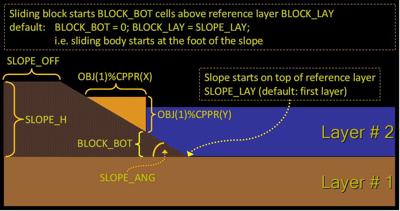
To define the starting position of the slope (i. e. bottom part) we first need to define a reference layer:
SLOPE_LAY Reference layer for slope : 1
The slope starts immediately on top of the reference layer. This parameter is an optional parameter. If it is missing, the first (bottom) layer is used as the reference layer.
The height of the slope is defined by
SLOPE_H Height of slope : 50
and is measured in cells starting from the reference layer. The slope angle is defined by a double precision value
SLOPE_ANG Slope angle : 45.D0
and is measured in degrees (0<SLOPE_ANG<90°). Extreme values for the slope angle, i.e. < 15° or > 75°, are recommended for experienced users only.
The slope can be shifted horizontally
SLOPE_OFF Slope offset : 20
to create a plateau of <SLOPE_OFF> cells. This parameter is optional. The default value is 0, i. e. the slope starts directly on the left side.
The material of the slope is (as usual) defined in the line
LAY_MAT Layer material : slope
For the sliding body we need to define a reference plane, too:
BLOCK_LAY Reference layer for slide body : 1
This parameter is optional. If not given, the same plane is used as for the slope. The distance between the bottom extent of the sliding body and the reference layer is defined by
BLOCK_BOT Bottom position of slide body : 20
This parameter is optional, too. Its default value is '0' which means that the sliding body is placed directly on top of the reference plane.
A positive value for BLOCK_BOT shifts the slide body up (if possible, the body is always placed in a way that the lower right corner of the sliding block touches the slope). A negative value indicates a slide body below the reference plane.
p((. Hint: When performing landslide simulations into water, it might be reasonable to select the first (bottom, i.e. bathymetry) layer as the reference layer for the slope, but the last layer (here: water) as the reference layer for the slide body. By doing so, we can easily define how deep below (or above) the water surface the sliding body initially is located.
The dimensions and the material of the sliding body are given as usual by the parameters
OBJRESH  horizontal resolution : 25
OBJRESV  vertical resulution   : 20
OBJMAT   material              : wetsand
Please note, that the width of the sliding body (i. e. horizontal resolution) defines the maximum width. The effective width depends on the angle of the slope. At angles > 45° the resulting width is smaller. At angles < 45°, the resulting width will match the given one, but the shape of the sliding body will turn from a triangle to a more complex one.
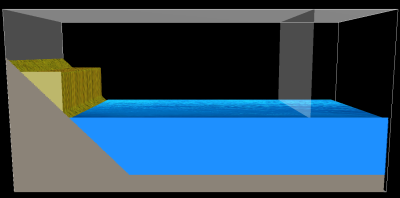
Here we provide some sketches of different possible setups:
- subareal
- submarine
- slide starts bottom
- slide on top of plateau
- slide partially on top of plateau
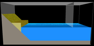
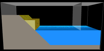
| original scenario | default_scenario |
|---|---|
 |
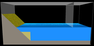 |
| The original scenario provided with iSALE | Using just default values. |
| BLOCK_LAY=2; BLOCK_BOT=0 | BLOCK_LAY=2; BLOCK_BOT<0 |
|---|---|
 |
 |
| Using BLOCK_LAY=2 to place sliding block relative to water surface (layer 2). By defining BLOCK_BOT=0 the slide body is placed directly on water level. | Defining BLOCK_LAY=2 and BLOCK_BOT<0 allows placing the sliding block below the water surface. |
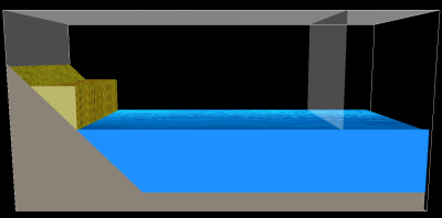
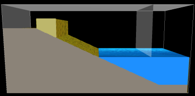
| SLOPE_OFF>0; BLOCK_BOT=0 | SLOPE_OFF>0; BLOCK_BOT>0 |
|---|---|
 |
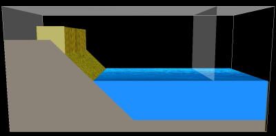 |
| Increase SLOPE_OFF to create a plateau. (Here: SLOPE_OFF=50, BLOCK_BOT=0) | Additionally increase BLOCK_BOT might place the sliding block partially on the plateu. and, hence, generates a more complex block geometry. |
| SLOPE_ANG=25 |
|---|
 |
| Change SLOPE_ANG to set the slope angle. |