I recently obtained a small laboratory spectrophotometer that had been discarded, and was surprised that the diffraction grating was directly driven by a 5-phase, ten wire Vexta motor. The optics were in perfect shape and useful for other projects, but there is little information on the web about how to drive a five phase stepper, and there are no working examples that I could find with Arduino.
Of course, you can buy a five phase driver from Oriental Motor Company (Vexta manufacturer) for about USD $200, but another option is to use an Arduino Pro Mini, and three much less expensive brushed DC motor drivers from Pololu.
The motor specs: Vexta PX33M-A-C6 0.21A, 33 Ohms per phase, 0.36 degrees/step. Ten wires.
The low current rating and moderate winding resistance means that direct drive from 5 to 6V is possible, avoiding the need for a chopper stepper driver. I decided to use three Pololu DRV8835 dual full bridge modules (only five H-bridges are used, leaving one free for other uses), and with dead simple code it is capable of executing 500 steps/sec from dead stop, without skipping a single step. Half step drive is available, for 2000 steps/revolution, capable of better than 500 steps/second.
See it move 1000 steps in real time:
Important design information in image below, used as a guide in creating the working example.

Improved step sequences for the pentagon connection are shown in the PDF file below from Oriental Motor.
MOTOR COIL LEAD IDENTIFICATION
I was not able to find a data sheet for this particular motor, but the windings on Vexta motors appear to obey a semi-consistent color code and lead assignment. There is nevertheless some confusion in available documentation. I started with this diagram, which supposedly reveals the coil and winding start/finish order:

But the motor connector on the original apparatus had white/yellow and grey/black reversed from the sequence above. The driver I put together works with the two problematic connections swapped (as long as both pairs of the two connections are reversed) but obeying the connector wire order resulted in the smoothest and presumably correct operation. That is, swap white/yellow and black/gray.
My decision to swap those leads is supported by the alternative assignment of wire colors and winding identifications in the PDF file below. Evidently Oriental Motor is not completely consistent with wire color codes.
For the pentagon wiring option, five half bridge drivers are used.
Stepper Driver Design and Construction
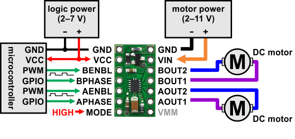
Wiring diagram for two of the phases, using the Pololu DRV8835 dual H bridge module (micro used was the Pro Mini). Image from Pololu product page:
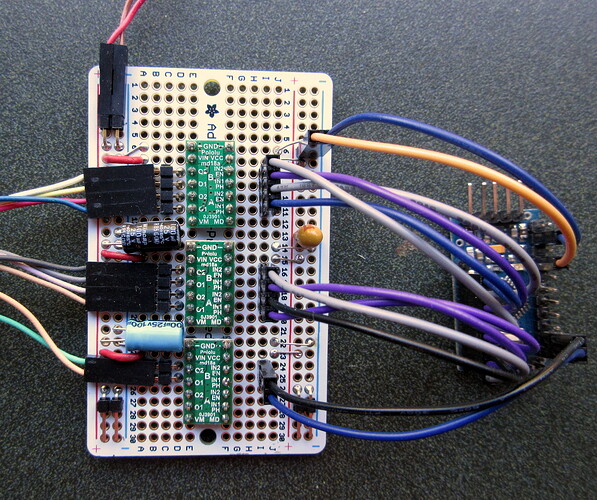
FINISHED DRIVER MODULE
The complete pin assignments and subsequent connections are detailed in the posted code.
Arduino Code is posted in two files, totally unoptimized and storage-optimized.