How to figure out which controller is underneath the display? #40
Comments
|
Identifying a particular board can be tricky. If vendor does not advertise the chip, generally I look at the existing driver to the board, if one is provided by the vendor, and cross-reference that against the protocol sheet PDFs of the controller chips. In some cases, I have resorted to using a USB logic analyzer to reverse engineer the communication of a driver to find out what it matches up with. 3.5" 320x480 SPI displays that I have encountered have been either ILI9486, ILI9486L, HX8357D or MZ61581. There is also ILI9488 controller that is 320x480, although fbcp-ili9341 does not support that one, I have not come across a ILI9488 that would be sold as 4-wire SPI. I would guess the KeDei is either a ILI9486 or a ILI9486L, those seem to be the two most widely used chips. MZ61581 seems to no longer be in active production. I have not attempted to visually identify any of the hardware circuitry on my boards. Let me know if finding the right controller is problematic, and I can look at posting photos of the displays I have, if that might help? |
|
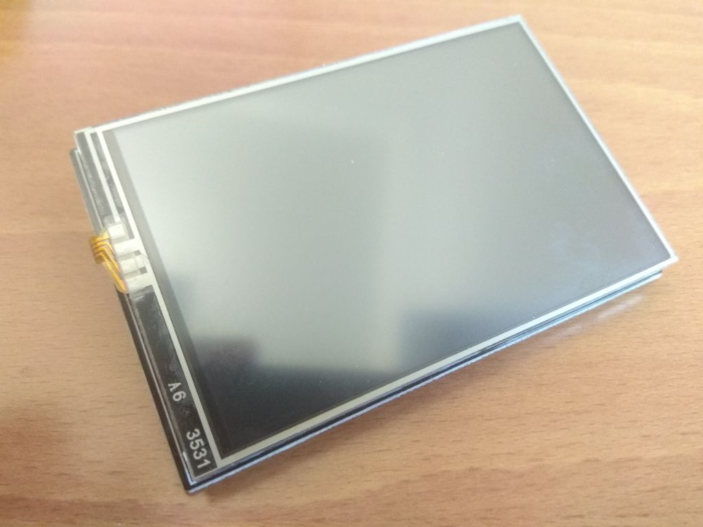
Thanks. I would really like to help with whatever I can to create a working version as the current "driver" and "OS-images" of the KeDei-website aren't well documentated nor work at all (for a RPi Zero). Please find attached pictures of what I have in front of me. |
|
Good photos, the pins are conveniently marked in the display. L_CS = Display Chip Select Unfortunately the absence of Data/Control (DC) pin means that this is a 3-wire SPI instead of 4-wire SPI display. Currently fbcp-ili9341 does not support 3-wire SPI displays. 3-wire SPI displays interleave command/data control bit and payload bits in the MOSI line. That is, instead of using a separate DC line that goes high for Data, low for Command, during which the MOSI line sends 8 bits (or 16 bits depending on word width used) for the payload, 3-wire SPI displays interleave this information to one line as serial 9 bits (or 17 bits) of This kind of interleaving has not been implemented. If you'd like to take a stab, this spot Line 103 in 2d4924b would probably be a good place to start. You'd be looking at expanding the Line 127 in 2d4924b but everything is essentially payload bits as far as SPI messaging is concerned, and waiting for CS toggles do not need to be performed, as happens e.g. in Line 141 in 2d4924b and somewhat more complex, in the DMA code in Line 586 in 2d4924b for anything that refers to |
|
Thanks for the very detailed explanation. I'm afraid that my programming knowledge doesn't reach that far into this topic to solve the work. Would you be interested in the display? For me it is quite worthless so that I would send it to you for free further development on this topic. |
|
Thank you for the most kind offer, it is much appreciated. However I am located in Finland, and it may not be worth the logistics to send the display over, because depending on where you live, customs may want to take part in the import, which may make it a pain. If you'd like to go ahead still, throw me a mail at jujjyl@gmail.com. I should say I cannot promise that I'll be able to get the display working either even if you do send it. It might be easiest to get one of the detected working displays for a known good configuration. |
|
Noticed that my Adafruit SSD1351 display can be soldered to work in 3-wire mode instead of 4-wire mode, and I was able to add support to fbcp-ili9341 in 3-wire mode after modifying the display. The support is now up in above commit. If you still have the 3-wire SPI display, it may be possible that the above support could also work on the KeDei display, although I am still not sure what controller it has. Also noticed there was an earlier conversation about KeDei at #27. |
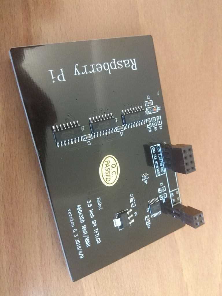
… SPI TFTLCD 480*320 16bit/18bit version 6.3 2018/4/9 display on screen. #40
|
Thanks for donating the display @Vvvsebastar . Got it now to work, uploaded first working version of code up at a backup branch https://github.com/juj/fbcp-ili9341/tree/kedei_v6_3_mpi3501 - that gets pixels showing on screen, although far from ready. It looks like according to https://github.com/goodtft/LCD-show the display is a "MPI3501" controller. That is a new one, have not encountered this before. The implementation was done by by sniffing the data bus from the working binary driver. Here is a summary of sorts:
Brief speed testing suggests that the controller can reliably handle a 33.333MHz SPI bus speed, but it was not able to do 40MHz. Because of the CS line juggling, effective bus speed remains lower, about 22mbps (22/33 ~ 67% utilization). Tallying up the above protocol framing with -75% / -50% wastage, the effective pixel bandwidth is something around 5.5mbps - 11mbps. The design choices lose around ~66%-85% of the bandwidth they could have had. Overall with all the above hindrances accumulated, frame rates in Quake run at around 15 interlaced frames per second (~7.5fps). The hardware design of this MPI3501 is out of this world in comparison with any of the other display controllers out there. I am pondering if I should even bother polishing and merging the above branch in, or just drop it. Even if the redundant CS line pumping turns out to be avoidable for pixel data uploads, the wasteful protocol framing design will hurt performance noticeably. The only good thing about this MPI3501 may be that it kind of makes ILI9486 look like a Ferrari (and HX8357 a jet airplane). |
|
@juj I am kinda confused, LCD-wiki shows that is has ILI controller. |

Hello,
I read the whole instructions and wanted to participate in your great work. I have just recently bought an Kedei 3.5 display (version 6.3 from August 2018) without HDMI. How can I figure out which controller is used?
Thanks
Sebastian
The text was updated successfully, but these errors were encountered: