
Figure 1: Exploring the environment of Uda-City
The goal of the project is to understand the phases of flight, to implement a simple flight plan within an event-driven programming paradigm, and to become familiar with sending commands to and receiving data from the drone. The report following consists of 5 sections: implementation, accuracy analysis, testing, potential improvements, and log processing. See also the backyard_flyer.py script for reference.
Flight state terminology
- manual: The vehicle is under manual control by the user.
- arming: Motors running at minimum throttle, rotors spinning at idle spin rate.
- takeoff: Power increases to the motors. Weight transfers from the landing gear to the lift mechanism (for a quadcopter, the propellers mounted on each arm). The vehicle goes from the ground to flying in the air, ascending to a target height.
- waypoint: While in flight, the vehicle moves to a three-dimensional reference point in space.
- landing: The vehicle descends to a target height (the ground or a landing platform). Weight transfers back to the landing gear. Power decreases to the motors.
- disarming: Power is removed from the motors, rotors spin down and stop.
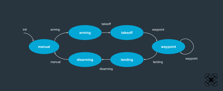
Figure 2: Phases of Flight
manual -> arming
    If global positioning is available:
    1. Take control of the drone
    2. Pass an arming command
    3. Set the home location to current position
    4. Transition to the ARMING state

arming -> takeoff
    1. Set target altitude to increase by 3.0m
    2. Command a takeoff to target_position
    3. Transition to the TAKEOFF state

takeoff -> waypoint
    1. If over 95% of the target height
    2. Transition to WAYPOINT state

waypoint -> waypoint
    1. If within 0.35 meters of the target position
    2. Command the next waypoint position
    3. Transition to WAYPOINT state

waypoint -> landing
    1. Command the drone to land
    2. Transition to the LANDING state

landing -> disarming
    1. Command the drone to disarm
    2. Transition to the DISARMING state

disarming -> manual
    1. Release control of the drone
    2. Stop the connection (and telemetry log)
    3. End the mission
    4. Transition to the MANUAL state
The 'box' is defined by the values self.NorthLegLength and self.EastLegLength and divided into increments using the value of self.steps which can range from 1 through 50.
The path of each leg of the box can therefore be traversed in whole or in partial increments. Five steps, each 2 meters apart, works well to hug the box. As the step value increases however, the path wobbles more. A step of one will drive the drone directly to the corner at the expense of overshooting the envelope. Additional analysis is provided in the next section.
When the drone reaches its final waypoint, it begins a landing procedure in the velocity callback as follows:
1. Check for global target elevation to be within 250 cm
2. Check for local target elevation to be within 150 cm
3. Check for minimal altitude variation (within 20 cm between callbacks)
This section describes additional analysis of the drone's behavior in positional flight mode. Initial observation of the drone movement revealed a large overshoot of the 'box' boundaries around which it is flying. For safety and efficiency, path-following inaccuracies cannot be ignored.
Figure 3 below is an overhead XY plot produced from the drone telemetry data. (See the log processing section below.) After heading north (along the Y axis), the drone begins turning eastward, but continues with a degree of momentum along the northbound vector. This results in an error of greater than 2 meters, overshooting the 12 meter line. The green shaded area overlays the ideal path. It is 0.7 meters wide and provides an error margin of 0.35 meters (13.8 inches) on each side of the path.

Figure 3: Stepping value 1
Targeting the half-way point along the legs improves the situation somewhat, but the drone still moves quite a bit outside of the green region.

Figure 4: Stepping value 2
Moving the intermediate waypoint to 1 meter prior to the target corner, produces slightly better results. The idea here is to ease the drone into and around the corner. Velocity probably still causes drift.

Figure 5: Stepping value 2 (the extra waypoint is 1 meter before the corner)
Dividing the path into 5 equal parts thereby targeting two-meter waypoints along the path ensures less error. This is the value coded into the backyard_flyer.py script at line 43, although it can be adjusted easily.
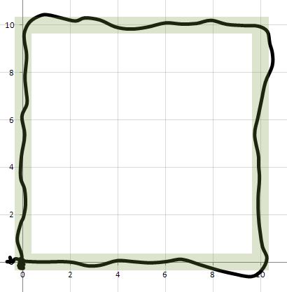
Figure 6: Stepping value 5 (evenly divided)
Targeting one meter waypoints along the box path keeps the drone within the green area, however signs of wobbliness are beginning.
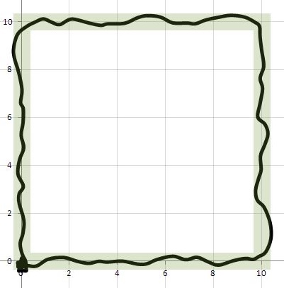
Figure 7: Stepping value 10 (evenly divided 1 meter targets)
Additional stepping values of 20 and 40 were explored which resulted in increasing amounts of wiggly paths. Though constrained to the green area, the vacillations appear to be chaotic.
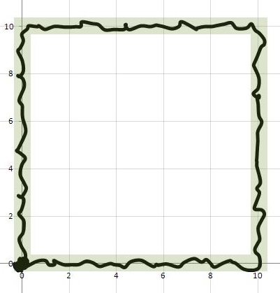
Figure 8: Stepping value 40 (evenly divided 0.25 meter targets)
By comparison, manual control offers its own challenges and yields the following plot. The telemetry is gathered from the simulator using the log.py script included in this repository.
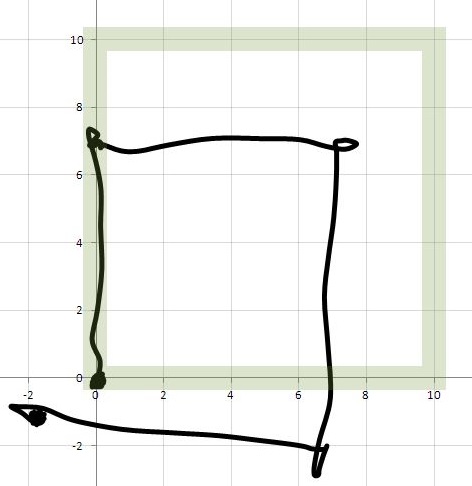
Figure 9: Manual flight (visual reference points are challenging)
While surveying the town within the simulator, the question arose as to whether alternate start points were possible. For example, the road is located 0.5 meters above the plane of the grass field while the row of housing has flat roofs which serve nicely as launch points at 15 meters elevation. This is a real-world scenario since launch pad elevations are not always sea-level.
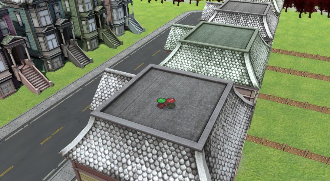
Figure 10: Launch position from a building rooftop (at 15 meters altitude)
At first, the drone did not behave correctly when landing - the disarm transition would not fire. Also, the fixed height of 3 meters meant the drone would attempt to dive off the building and drop to a literal 3 meter altitude. These two situations indicated that a relative starting point would need to be saved and checked such that a more robust controller can start the drone from any height. Upon launch, the vehicle should ascend 3 meters above its starting altitude, perform its box maneuver at that new relative altitude, and then descend back to the starting position, landing on the original launch pad.
In Figure 11 below, the drone successfully launched from the top of the welcome sign (at 16 meters altitude), ascended 3 meters, performed the box pattern at 19 meters altitude, and returned to the start position (landing on the top of the sign).
These tests also informed adjustments to the landing criteria, increasing slightly the tolerance differences.

Figure 11: Launch/land position from atop the welcome sign
The finite state machine in its present form (as given in the classroom) might be recast into the diagram below (Figure 12). A common armed state allows for additional missions without first transitioning to the manual state.
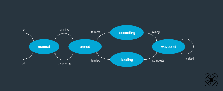
Figure 12: Alternative finite state diagram
Suggestions for improvement of the simulator...
- Flatten the Unity colliders on the rooftops of both the pink building and the white building marked "the office" to allow landing.
- Allow for passage through the tunnel at the base of the large pink building.
- Add some obstacles in the western field, including a few landing platforms at varying heights.
- Drone always points North and ignores positional heading parameter.
The log files are visualized as follows:
- Import to Microsoft Excel
- Text to columns, delimited by a comma
- Sort rows by column A
- Find the first MsgID.LOCAL_POSITION x,y pair
- Select until the last pair
- Insert a scatter plot with smooth lines
- Swap the x and y values
- Set graph size and format styles
- Screen capture
End of report
In this project, you'll set up a state machine using event-driven programming to autonomously flying a drone. You will be flying a quadcopter in the Unity simulator. After completing this assignment, you'll be familiar with sending commands and receiving incoming data from the drone.
The Python code you write is similar to how the drone would be controlled from a ground station computer or an onboard flight computer. Since communication with the drone is done using MAVLink, you will be able to use your code to control an PX4 quadcopter autopilot with little modification!
If you haven't already, download the version of the simulator that's appropriate for your operating system from this repository.
If you haven't already, set up your Python environment and get all the relevant packages installed using Anaconda following instructions in this repository
git clone https://github.com/udacity/FCND-Backyard-FlyerThe required task is to command the drone to fly a 10 meter box at a 3 meter altitude. You'll fly this path in two ways: first using manual control and then under autonomous control.
Manual control of the drone is done using the instructions found with the simulator.
Autonomous control will be done using an event-driven state machine. First, you will need to fill in the appropriate callbacks. Each callback will check against transition criteria dependent on the current state. If the transition criteria are met, it will transition to the next state and pass along any required commands to the drone.
To communicate with the simulator (and a real drone), you will be using the UdaciDrone API. This API handles all the communication between Python and the drone simulator. A key element of the API is the Drone superclass that contains the commands to be passed to the simulator and allows you to register callbacks/listeners on changes to the drone's attributes. The goal of this project is to design a subclass from the Drone class implementing a state machine to autonomously fly a box. A subclass is started for you in backyard_flyer.py
The Drone class contains the following attributes that you may find useful for this project:
self.armed: boolean for the drone's armed stateself.guided: boolean for the drone's guided state (if the script has control or not)self.local_position: a vector of the current position in NED coordinatesself.local_velocity: a vector of the current velocity in NED coordinates
For a detailed list of all of the attributes of the Drone class check out the UdaciDrone API documentation.
As the simulator passes new information about the drone to the Python Drone class, the various attributes will be updated. Callbacks are functions that can be registered to be called when a specific set of attributes are updated. There are two steps needed to be able to create and register a callback:
- Create the callback function:
Each callback function you may want needs to be defined as a member function of the BackyardFlyer class provided to you in backyard_flyer.py that takes in only the self parameter. You will see in the template provided to you in backyard_flyer.py three such callback methods you may find useful have already been defined. For example, here is the definition of one of the callback methods:
class BackyardFlyer(Drone):
    ...

    def local_position_callback(self):
        """ this is triggered when self.local_position contains new data """
pass- Register the callback:
In order to have your callback function called when the appropriate attributes are updated, each callback needs to be registered. This registration takes place in you BackyardFlyer's __init__() function as shown below:
class BackyardFlyer(Drone):

    def __init__(self, connection):
        ...

        # TODO: Register all your callbacks here
        self.register_callback(MsgID.LOCAL_POSITION, self.local_position_callback)
Since callback functions are only called when certain drone attributes are changed, the first parameter to the callback registration indicates for which attribute changes you want the callback to occur. For example, here are some message id's that you may find useful (for a more detailed list, see the UdaciDrone API documentation):
MsgID.LOCAL_POSITION: updates theself.local_positionattributeMsgID.LOCAL_VELOCITY: updates theself.local_velocityattributeMsgID.STATE: updates theself.guidedandself.armedattributes
The UdaciDrone API's Drone class also contains function to be able to send commands to the drone. Here is a list of commands that you may find useful during the project:
connect(): Starts receiving messages from the drone. Blocks the code until the first message is receivedstart(): Start receiving messages from the drone. If the connection is not threaded, this will block the code.arm(): Arms the motors of the quad, the rotors will spin slowly. The drone cannot takeoff until armed firstdisarm(): Disarms the motors of the quad. The quadcopter cannot be disarmed in the airtake_control(): Set the command mode of the quad to guidedrelease_control(): Set the command mode of the quad to manualcmd_position(north, east, down, heading): Command the drone to travel to the local position (north, east, down). Also commands the quad to maintain a specified headingtakeoff(target_altitude): Takeoff from the current location to the specified global altitudeland(): Land in the current positionstop(): Terminate the connection with the drone and close the telemetry log
These can be called directly from other methods within the drone class:
self.arm() # Seends an arm command to the droneTo log data while flying manually, run the drone.py script as shown below:
python drone.pyRun this script after starting the simulator. It connects to the simulator using the Drone class and runs until tcp connection is broken. The connection will timeout if it doesn't receive a heartbeat message once every 10 seconds. The GPS data is automatically logged.
To stop logging data, stop the simulator first and the script will automatically terminate after approximately 10 seconds.
Alternatively, the drone can be manually started/stopped from a python/ipython shell:
from udacidrone import Drone
from udacidrone.connection import MavlinkConnection
conn = MavlinkConnection('tcp:127.0.0.1:5760', threaded=False)
drone = Drone(conn,tlog_name="TLog-manual.txt")
drone.start()
If threaded is set to False, the code will block and the drone logging can only be stopped by terminating the simulation. If the connection is threaded, the drone can be commanded using the commands described above, and the connection can be stopped (and the log properly closed) using:
drone.stop()When starting the drone manually from a python/ipython shell you have the option to provide a desired filename for the telemetry log file (such as "TLog-manual.txt" as shown above). This allows you to customize the telemetry log name as desired to help keep track of different types of log files you might have. Note that when running the drone from python drone.py for manual flight, the telemetry log will default to "TLog-manual.txt".
The telemetry data is automatically logged in "Logs\TLog.txt" or "Logs\TLog-manual.txt" for logs created when running python drone.py. Each row contains a comma seperated representation of each message. The first row is the incoming message type. The second row is the time. The rest of the rows contains all the message properties. The types of messages relevant to this project are:
MsgID.STATE: time (ms), armed (bool), guided (bool)MsgID.GLOBAL_POSITION: time (ms), longitude (deg), latitude (deg), altitude (meter)MsgID.GLOBAL_HOME: time (ms), longitude (deg), latitude (deg), altitude (meter)MsgID.LOCAL_POSITION: time (ms), north (meter), east (meter), down (meter)MsgID.LOCAL_VELOCITY: time (ms), north (meter), east (meter), down (meter)
Logs can be read using:
t_log = Drone.read_telemetry_data(filename)The data is stored as a dictionary of message types. For each message type, there is a list of numpy arrays. For example, to access the longitude and latitude from a MsgID.GLOBAL_POSITION:
# Time is always the first entry in the list
time = t_log['MsgID.GLOBAL_POSITION'][0][:]
longitude = t_log['MsgID.GLOBAL_POSITION'][1][:]
latitude = t_log['MsgID.GLOBAL_POSITION'][2][:]
The data between different messages will not be time synced since they are recorded at different times.
After getting familiar with how the drone flies, you will fill in the missing pieces of a state machine to fly the drone autonomously. The state machine is run continuously until either the mission is ended or the Mavlink connection is lost.
The six states predefined for the state machine:
- MANUAL: the drone is being controlled by the user
- ARMING: the drone is in guided mode and being armed
- TAKEOFF: the drone is taking off from the ground
- WAYPOINT: the drone is flying to a specified target position
- LANDING: the drone is landing on the ground
- DISARMING: the drone is disarming
While the drone is in each state, you will need to check transition criteria with a registered callback. If the transition criteria are met, you will set the next state and pass along any commands to the drone. For example:
def state_callback(self):
	if self.state == States.DISARMING:
    	if !self.armed:
        	self.release_control()
        	self.in_mission = False
        	self.state = States.MANUAL
This is a callback on the state message. It only checks anything if it's in the DISARMING state. If it detects that the drone is successfully disarmed, it sets the mode back to manual and terminates the mission.
After filling in the appropriate callbacks, you will run the mission:
python backyard_flyer.pySimilar to the manual flight, the GPS data is automatically logged to the specified log file.
Two different reference frames are used. Global positions are defined [longitude, latitude, altitude (pos up)]. Local reference frames are defined [North, East, Down (pos down)] and is relative to a nearby global home provided. Both reference frames are defined in a proper right-handed reference frame . The global reference frame is what is provided by the Drone's GPS, but degrees are difficult to work with on a small scale. Conversion to a local frame allows for easy calculation of m level distances. Two convenience function are provided to convert between the two frames. These functions are wrappers on utm library functions.
# Convert a local position (north, east, down) relative to the home position to a global position (lon, lat, up)
def local_to_global(local_position, global_home):

# Convert a global position (lon, lat, up) to a local position (north, east, down) relative to the home position
def global_to_local(global_position, global_home):- Filled in backyard_flyer.py