Python calibration routine #120
Conversation
|
It might be better to calibrate the Constant Current A_DAC by shorting the output terminals. This would allow us to use the full current range |
|
Excellent writeup! |
|
I tried this and the first step (Input Voltage Calibration) seems to be working well. |
|
.. well that's certainly very odd. It's only sweeping the V_DAC values and reading back the V_ADC values so I can't see what's wrong. This kind of looks like your issue. Perhaps it's a dependency of matlibplot? |
|
@Xenoamor So I tried it again, with a 12V and my 48V supply:
and as you can see, step 1 works, step 2 is kind of completly off. Same thing applied for 12V and 20V supply test, with calibration-reset before: I must also report that - if I attach the correct (low) powersupply initially to the DPS and start the -C process, the display of the DPS changes to a calibration screen. As soon as I exchange the power supply to the higher voltage one and contine, that display stays at the old CV mode - and also in step 2 it does not change from that. Do I need to manualy do something to change it into the calibration mode? :) Thanks a lot :) |


|
It might take me a couple days to get round to it but for now you can manually change to the calibration screen from the CV screen when you power it up for the second time before proceeding in the python routine. This should then work as expected You can manually change to this screen by pressing the M1 and M2 buttons at the same time |
|
I can confirm the problem stated in #129 . After switching to the second power source and switching the DPS5005 manually to the calibration mode, using M1+M2, I was able to calibrate it, as shown below. The quality of the calibration was severly off, however, I need to dig deeper into this - I assume my load resistance is very bad (acutally I just pulled some 0.125 Watt, 33 kOhm resistor from the stack - not the best thing to test something like this..). The DPS5005 did output 6.1 V for a setpoint of 5V and 19V for a setpoint of 12V, using a 20V power supply. I assume that both voltages were to close to each other and I should try to calibrate with 5V and 48V. However, is there another thing which has to be changed in the firmware for the DPS5005 to support this style of "multi-power-brick-calbiration"? If so, I can test the result as soon as it is published to the repo. Also: Regarding the power supply: I opened a bug report a while back #111 - the problem was not the usb ttl serial device, and persisted, meaning, that the DPS5005 upon boot about 4/5 times while trying to power it with my trust old 48 V power supply (which I needed, as I have to output at around 38 V for certain applications and could do so successfully in the past with the original firmware). I am not sure wheter I just killed my DPS5005 regarding my very unfriendly and bad flashing attempt in #100 - however, the rest is still working, so I will investigate and try to calibrate the DPS5005 with the autocalibration provided here as soon as it is regarde ok for use with two different power bricks :). 12V and 20V supply: |


|
Hmmm... It seems like your device is fairly noisy at the top ends. Also your resistor is certainly unsuitable for this. You really need something around the sub 100R range. |

|
Thank you very much for your answer. So everything below 100 Ohm should work? Then I will try and see, I probably should have some 47 Ohm or something like this lying around here. I use an UNI-T UT61E - it also got an 10A input, however, the manual states that currents above 5A are only allowed to be connected for less than 10 seconds - otherwise it will be damaged. So, I am unsure about this option :) |
|
So, I got some good news - I tried the calibration again. This time, I used an AUKEY 5V USB Brick and my 48V PoE Power Supply. I also introduced as "load resistor"(its a bit of a joke, wait for it...) a 1000 Ohm, 0.25 Watt and 0.1% Resistor. Reason I choose this, even though it should be under 100 Ohm, is the fact that I know the wattage precisely and with 0.1%, its of higher accuarcy. I also made sure to have a proper connection on all IN and OUT pins of the DPS5005. This time, it really worked out and I got a good calibration which is near perfect. Leasons learned:
The Calibration Report for my Unit is following: Best regards, |


|
Thanks for the great write-up @nmaas87. Looks like you got lucky with the gradient detection algorithms though which is why it worked out. I'll make a new issue for this and improve it |
Okay this is a bit of a mammoth commit so I'll try my best to walk through the code here. (FYI I believe this is all PEP8 compliant). All images are generated from the calibration routine I have run on my DPS5005
The calibration routine requires the following equipment:
The routine is split into the following 4 stages which are executed sequentially:
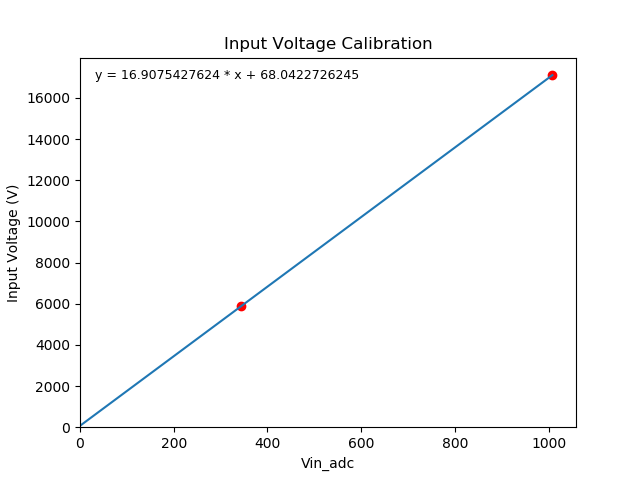
1. Input Voltage Calibration
The input voltage calibration consists of powering the device from two known voltages. The further apart these voltages are the more accurate the calibration for this stage will be.
I used another DPS5005 to generate the two voltages. In my instance these were 5891mV and 17110mV. It is best to measure these voltages using a multimeter at the input terminals of the DPS under test.
2. Output Voltage Calibration (ADC & DAC)
The output voltage calibration consists of outputting two DAC values and recording the real output voltage with a multimeter. This in turn can be used to calibrate not only V_DAC but also V_ADC
As the relationship between the input voltage and the maximum output DAC is currently unknown this must be determined. This is done by sweeping a range of V_DAC values and plotting them against V_ADC

The blue line here is the determined maximum output DAC value. This is calculated by looking for the first point where the gradient between two consecutive data points is less then 0.1. Please note it is important this is done open circuit due to #7
Now that we know our workable range for V_DAC we can ask the user to give us two multimeter readings of the output at 10% and 90% of this. This in turn allows us to compute the coefficients for V_DAC and V_ADC

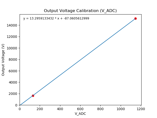
As V_ADC is now correctly calibrated we will now be using this to measure any output voltages from here on out
3. Output Current Calibration (ADC)
The output current ADC calibration routine works on the principle that we have a fixed resistance load (not necessary true with heat) and that we can rely on the calibrated V_ADC value to determine the output current using
Vout / RloadWe must first determine what is the safe maximum output voltage for this load. This depends on three factors:
90% of the input voltage5A / Rloadsqrt(Rwattage * Rload)The safe maximum output voltage is then the minimum of these.
We can now sweep our V_DAC output up to this value and use the
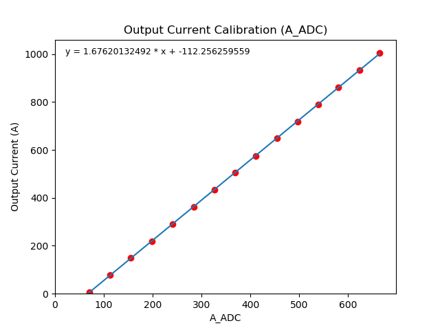
V_ADC / Rloadequation to plot the output current against the A_ADC value to determine our coefficientsThe constant current calibration routine works by sweeping the A_DAC value across it's workable range to determine the output current this generates.
As we do not know what the safe working range is for the A_DAC value (one that doesn't exceed the load's wattage) we set the maximum output voltage via V_DAC using the maximum output voltage determined in step 3. This means that we can not exceed this as if we do it will voltage limit.
Now this is limited we can sweep the full range of A_DAC values safely to determine it's working range

The two blue lines here are 10% in from the minimum and the maximum
Now that we know our working region we can sweep within it and plot it against the output current
V_ADC / RloadSummary
For me the voltage calibration is razor sharp. However the constant current calibration is not great. I think some of this is because of #7 but I think it mainly comes down to my workable range being very small (180ma to 850ma) as seen in the "Output Current Sweep" graph. This is caused by me not having an ideal load resistor
To enable the graph generation used to make the above images change the global variable
calibration_debug_plottingtoTrue