eilasung FDD-UDD U144K display pinouts? #456
Comments
|
Also, if someone could help me with the rotary encoder pin-outs and speaker pin-outs, I should be able to complete the project. |
|
Now to figure out the rotary encoder and speaker pin-outs... |


|
This version of PCB has stopped production https://github.com/keirf/FlashFloppy/wiki/Gotek-Compatibility |
|
Thanks. I will purchase one of the new units. For now, since I have purchased two of these units and all the hardware to mod them, I am hopeful for collaboration to get these two modded. |
|
I may add support for this as part of supporting the new 48pin Artery MCU boards. Since they too have no rotary header. |
Thanks @keirf. For clarity, are you saying that I cannot connect a rotary encoder to the Eilasung FDD-UDD U144K board? |
|
Yes there's no header for the pins currently used for rotary encoders |
|
@keirf I realize there are no pins, but are there any solder points on the board that could be used for the CLK, DT, SW, + and GND signals though? Unfortunately this is the only page with some information that I have found. It's very sparce on this board but I am just trying to work with what I have. |
|
With the help of a friend. I have been able to figure out how to hook up the rotary encoder and the speaker. I am including a diagram with colored areas on where to hook up the encoder.
From the email that he sent me: Reference Keirf rotary encoder image, that shows green, blue and red wires for the rotary. You'll see where those 3 colors are hooked up in the picture. I used the same green, blue and red color to denote. You can connect GND to the same GND as the OLED, and same for VCC/3V3, but look at the reference to when the orange dotted line is needed. The swiggle I drew shows where pin one is on the LQFP64 chip, it is the dimple on the chip. There might be other circles on the chip, but the dimple that is the smaller hole denotes pin 1. To make sure you have the orientation on the chip right, check ohm between 48/VDD_2, 32/VDD_1 and 64/VDD_3, all these should be connected, 0 ohm to each other. For the speaker, one wire goes to GND, the other goes to 16/PA2, circled in black on my attached picture. Microscope is nice for this, magnifying glass at minimum. For the pins on the chip, they might be pulled to a via, so then it's much easier to solder to the via instead of directly to chip pin. I will be uploading the completed photos once I get it all together and test. |

|
My plan going forward is to connect to any VIAs that I can find. Once I have that all done, I will do a photo of the board with the connections diagrammed properly on the photo. More to follow as I go through the process. |
|
Here is a photo of where you can solder the leads for the rotary encoder and the speaker. Enjoy! @keirf you can close this one now.
|

|
Just to add to this, there's no need to solder to vias for the speaker. I've traced the connection out to J3 header and works great on mine. My board is marked with c2013 instead of c2007 so I'm not sure what's changed. J5 appears to be connected to rotary SW but I haven't tested yet. Unfortunately it looks like DT and CLK aren't connected on the PCB to anywhere. |
|
I can confirm J5 is the rotary SW. |
|
I modified my FDD-UDD U144K with an OLED Display a Rotary encoder and a speaker. It's working very fine on my Amiga. I want to use it also on my Atari 1040STF but can't find any information about setting jumpers to get it working. On Amiga is working for me as DF0 (jumper on J2) or DF1 (jumper on J1) but I can't run it on my Atari. After connecting to Atari and starting TOS there is clear desktop no one's drive icons drive visible neither A neither B. I connected it on twisted FDD cables. |


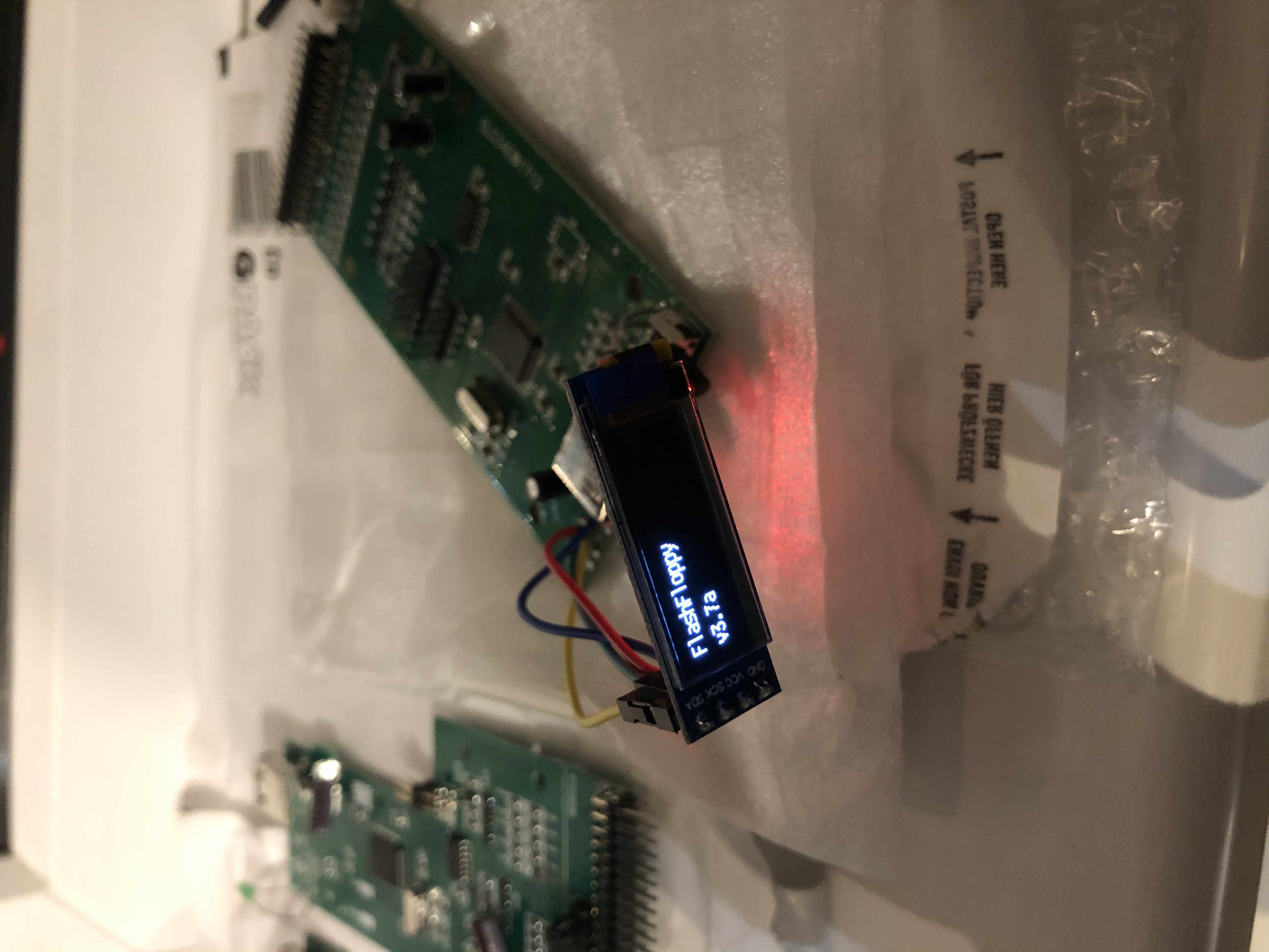
I am trying to find the correct pinouts on this board to be able to connect up a OLED display. I have de-soldered the old 7-segment display. The old display only shows GND. I need to know which pads to connect the VCC, SCL and SDA pins to. I found a two year old issue and someone had posted a photo of the display connected up but when I zoom in, it is very blurry and I can't make out which pins go to which pads on the board. I will attach that image below.
The text was updated successfully, but these errors were encountered: