EPROM Adapter
This document covers three generations of adapter:
- 1st gen: 27C400 only. No configuration jumpers.
- 2nd gen: 27C400/800/160. Two jumpers (A18-A19)
- 3rd gen: 27C400/800/160/322, Three jumpers (A18-A20), '322-mode switch.
The supported EPROM parts are:
- 27C400: 40-pin, 4Mbit (256k x 16-bit, 512k x 8-bit)
- 27C800: 42-pin, 8Mbit (512k x 16-bit, 1M x 8-bit)
- 27C160: 42-pin, 16Mbit (1M x 16-bit, 2M x 8-bit)
- 27C322: 42-pin, 32Mbit (2M x 16-bit, no 8-bit access mode)
The adapter converts the pin-outs of the above parts (which is similar to contemporary DIP-packaged mask ROMs) to 27C4096 pin-out as supported by the readily-available and cheap TL866 series of USB programmers.
- 1x DPDT Push switch, 6pin, 7mm x 7mm
- 1x 48pin ZIF socket
- 2x 20pin male header pins
- 3x 3pin male header pins (A18, A19, A20)
- 3x 2pin header jumpers (for selecting A18, A19, A20)
- 3x 10kohm 0805 resistors (R1, R2, R4)
- 1x 1kohm 0805 resistor (R3)
- 1x MMBT3906, SOT23 package (Q1)
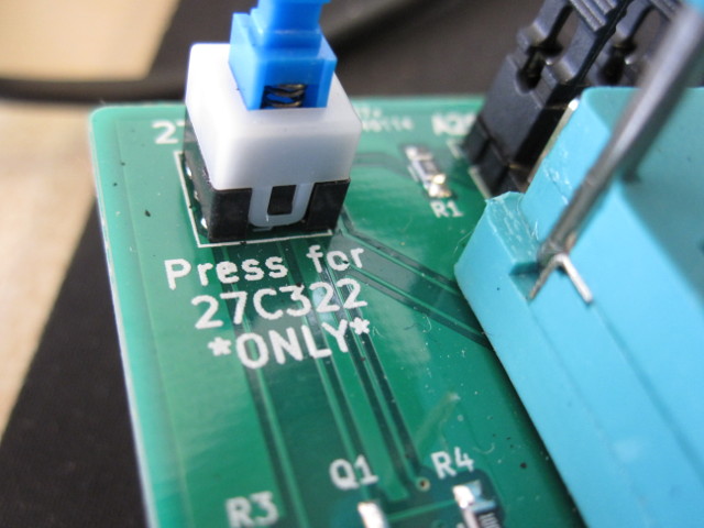
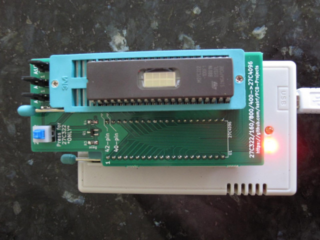
If you received a kit of parts for self assembly, refer to the picture below for a general idea of how things fit together. Note that the 1K resistor belongs at location R3 (marked 'Base') and that one of the 10K resistors is soldered to the underside of the PCB. Also take care to install the push switch the correct way round (see picture).
Insert the programming adapter into the TL866 with the socket handles adjacent to each other. Insert the EPROM into the lowest-possible position in the adapter and with pin 1 nearest the handle.
If your adapter has a 27C322-mode push switch, press it always and only when programming 27C322 parts.
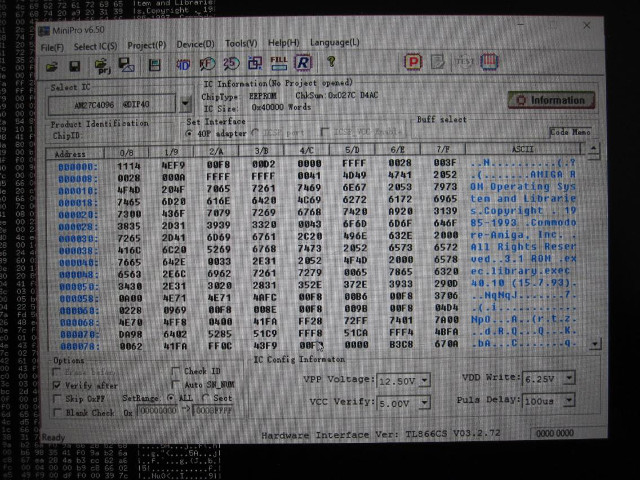
Launch the MiniPro software, select AMD 27C4096 DIP40 device, and
deselect Check ID. You may also optionally reduce VPP Voltage to
12.50V, depending on your EPROM's datasheet and programming success.
The EPROM can now be accessed as if it were a 27C4096 device, 512kB at a time, as configured by the bank-switching handled jumpers:
- 27C400: no need to set jumpers, program all 512kB in one pass.
- 27C800: program in 2 512kB passes: A18=0 (bank 1), then A18=1 (bank 2)
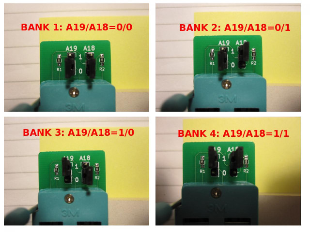
- 27C160: program in 4 512kB passes: A19/A18=00,01,10,11 (banks 1,2,3,4)
- 27C322: program in 8 512kB passes: A20/A19/A18=000,001,010,011,100,101,110,111 (banks 1,2,3,4,5,6,7,8)
If you suffer write or verify errors when programming, try these steps:
-
Make sure the EPROM is fully blank before programming it (
Device -> Blank Check). All EPROMs available today are second-hand 'pulls' and sellers aren't always careful when erasing before resale. -
Open and close the adapter's ZIF lever a few times, and reposition the EPROM squarely in the socket.
-
Try adjusting
VPP Voltagebetween12.50Vand13.50V. Subjectively I have had greater success at the higher voltage and it gives headroom for voltage losses in transferring VPP through the adapter's logic. -
Programming errors will occur from time to time, and of course the chances increase the larger the device. It makes sense to invest in a UV eraser. These are available at low cost on Ebay from the Far East for around £10-15 ($15-20). Most devices will be erased after 10 to 20 minutes under UV light.