Installation
The switcher's underlying EPROM must be plugged into your Amiga's
EPROM socket. Pin 1 of the EPROM is at the end marked
GND/DCLK/DIO/3.3 on the switcher PCB. Be careful when inserting not
to bend any of the EPROM pins.
The ROM is directly compatible with any single-ROM Amiga with a 42-pin ROM socket. In this case insert the ROM with its pin 1 in pin 1 of the socket (however since this pin is cut short, it will of course not make contact with the socket).
If the Amiga has a 40-pin socket then ensure that pin 31 of the socket is connected to VCC. This is true for A500 Rev 6 and later, A500 Plus, and A600, among others. If compatible, insert the ROM with pin 2 in pin 1 of the socket (ie. the shortened pins overhang the socket).
Attach the PC motherboard speaker to pins G and B8 of the switcher. Attach A8 of the switcher to the Amiga's reset line. A jumper wire and probe clip are supplied for this purpose (separately if supplied in kit form; soldered together in assembled form).
WARNING: The ROM will not work reliably until connected to the reset line. It will switch randomly between the programmed Kickstart images causing crashes.
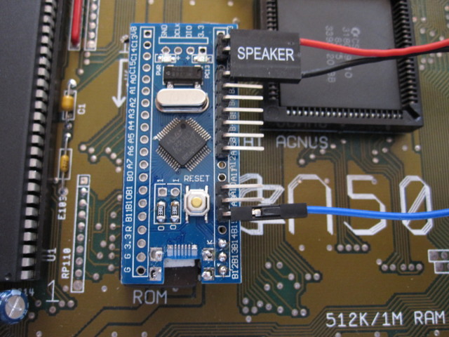
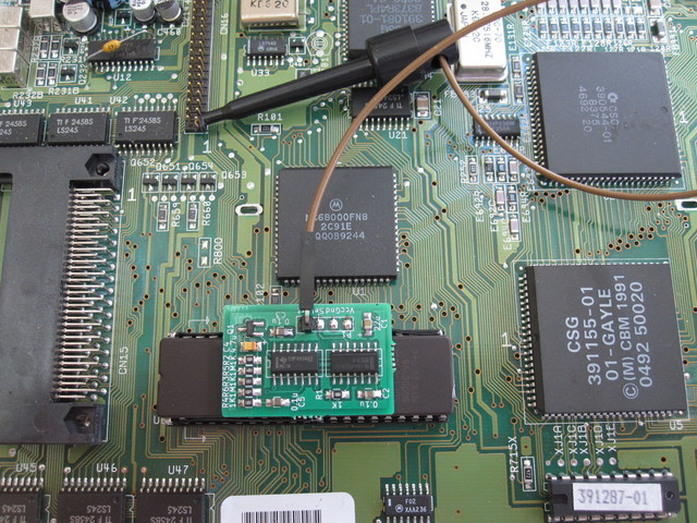
The ROM is installed with the switcher's header pins pointing to the right (towards the trapdoor).
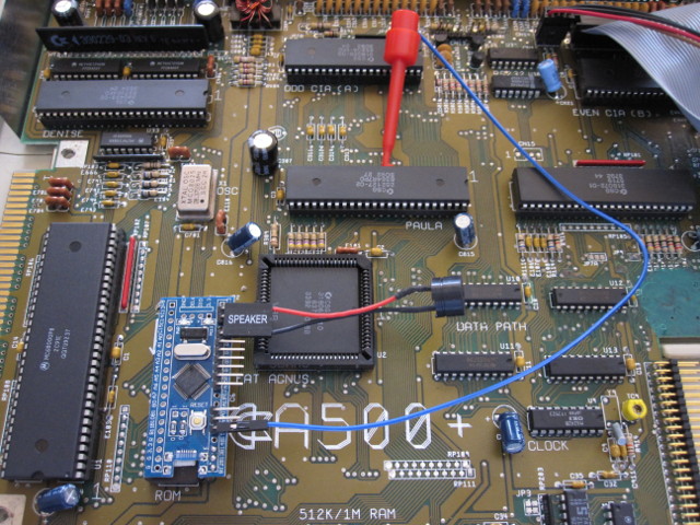
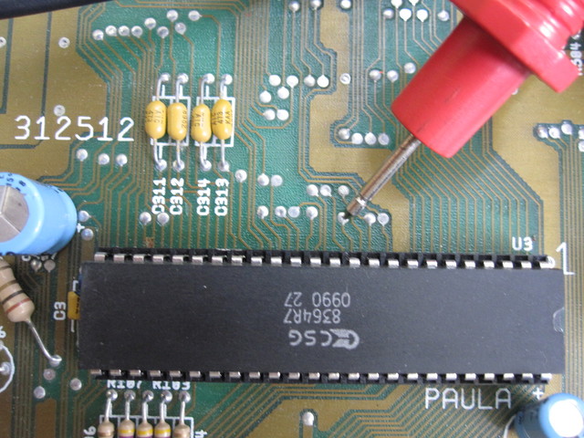
Clip the reset wire to the leg of any DIL chip connected to the _RST line. Paula pin 11 is a good choice (see picture). You may need to bend and/or open up the probe clip a little to hook it around the chip pin -- make sure to retract the clip as far as possible and snug the probe up against the pin, and check that the clip does not touch any adjacent pin.
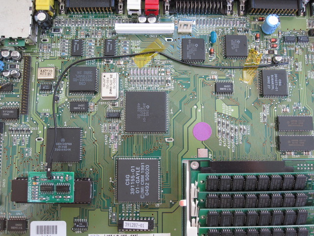
If you want a more permanent connection, _RST is available at various vias on the A500 motherboard (eg. there is one near Paula on at least Rev 6A: see below) or at resistor array RP101. A buzz test with a multimeter for continuity with Paula pin 11 will confirm that a via or track carries _RST.
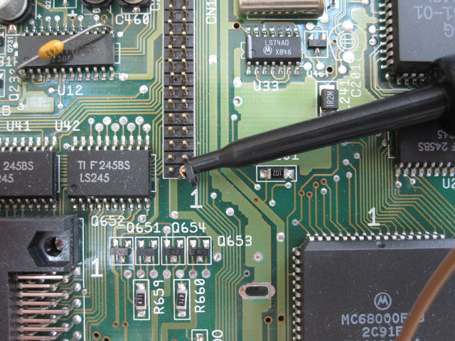
Similar to A500 you can clip to any DIL chip connected to the _RST line: eg. Paula pin 11, 68000 pin 18, or Gary pin 41.
The ROM is installed with the switcher's header pins pointing towards the rear of the machine.
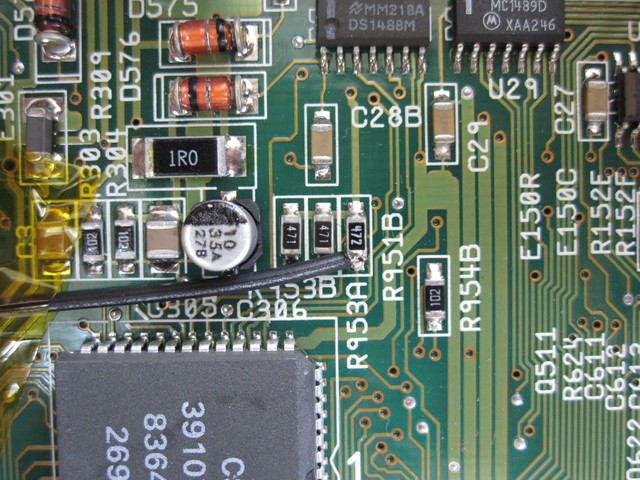
Clip the reset wire to pin 1 of the IDE port if it is unused. (NB. following pictures are of an earlier version of the switcher, however the same principles apply for locating the reset line).
Otherwise you will need to solder to resistor R951B near Paula.