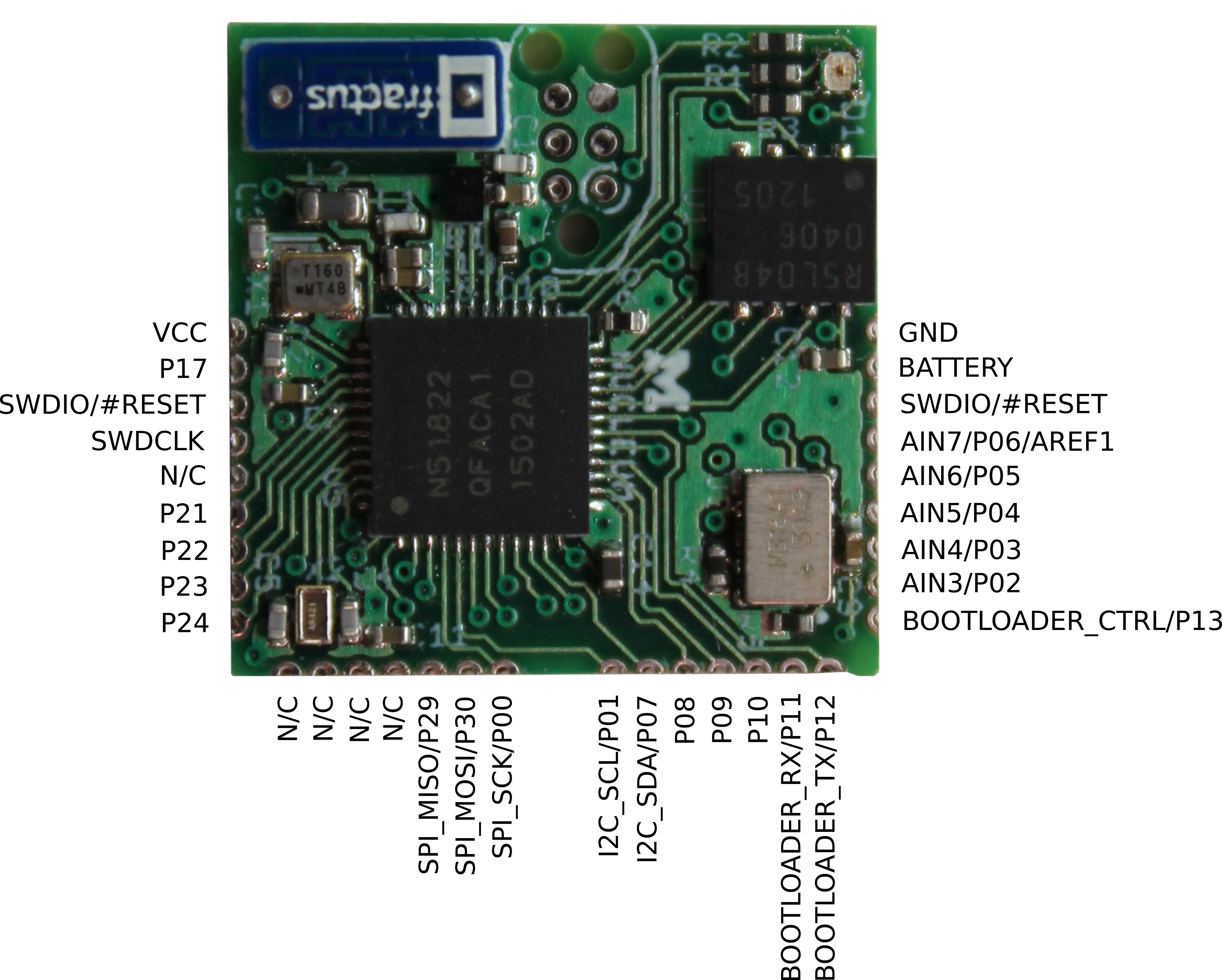
Nucleum is a ½ inch² drop-in sensor node module designed to enable rapid prototyping of Bluetooth Low Energy embedded devices. The core of Nucleum is the NRF51822 SoC with an Arm Cortex M0 and BLE radio stack. Nucleum also includes an antenna, 4 kilo-bytes of non-volatile FRAM memory, an RTC, and a tri-color LED.
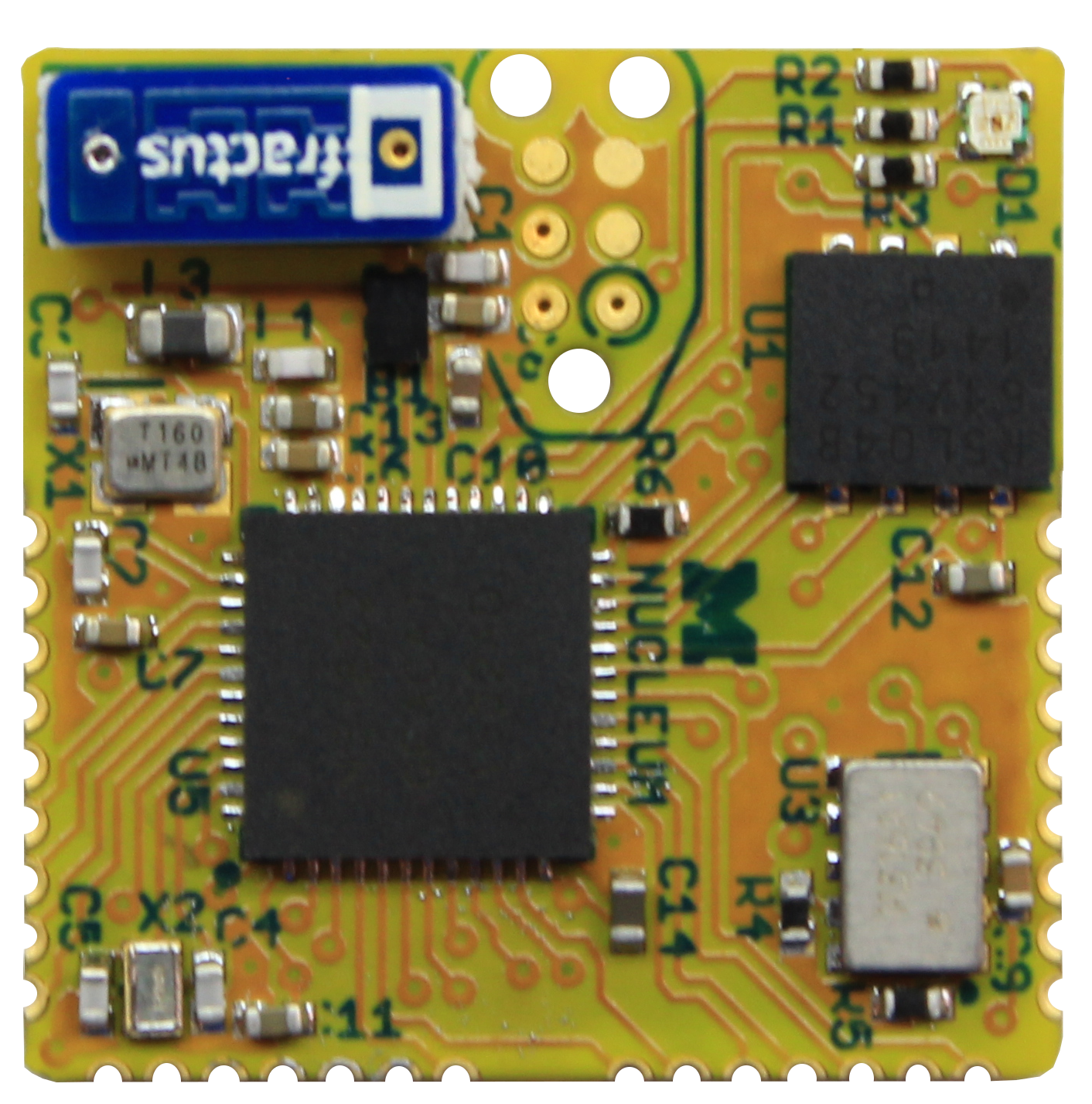
Nucleum is designed to have two different usage patterns. First, three sides of the device have castellated headers allowing Nucleum to be directly soldered onto a carrier PCB. Nucleum handles all of the computation and communication while the carrier board supplies power and attaches sensors or other peripherals. In the second option, Nucleum can function as a complete sensor node. On the bottom are pads for a regulator and a battery. If needed, a peripheral or sensor board can be stacked on top using the headers as a bridge.
Nucleum is directly derived from Atum. It changes the radio protocol to BLE and adds an on-board programmer. Like Atum, it is intended to be a building block for sensor platforms that only includes the features that a sensor board needs. Visit the Atum page to read more about its origins.
Nucleum is the latin accusative form of 'Nucleus' which, like Atum, represents a basic building block of matter. The 'LE' in the spelling of Nucleum indicates its use as a Bluetooth Low Energy prototyping board, and the 'UM' at the end of Nucleum represents Nucleum's development at the University of Michigan.
To use the NRF51822, you should run bare metal code that is built around the Nordic SDK and software BLE stack (known as a softdevice). We provide some examples and drivers for the chips on the Nucleum board. For more information on getting started please see software/README.md.
Nucleum PCBs are panelized into 5x8 panels. They are designed to be 1mm thick to allow for easy soldering of the castellations on the edge of the board.
If you use the battery and regulator on the bottom of the board, you will have to populate a 0 Ohm resistor to select regulated voltage. The selection is between 1.8V and 3.0V. Position A is 1.8V and position B is 3.0V. The 1.8V selection was included because it significantly lowers power draw on the NRF51822, but at this voltage the RTC and FRAM may not work. Please see the hardware pdf to locate this resistor selector. DO NOT populate both position A and B; this will short the battery.