Check consandstuff.github.io/sound-voltex for full instructions.
CODE INSTRUCTIONS:
-
Download and install ARDUINO IDE v1.8 https://www.arduino.cc/en/Main/OldSoftwareReleases#previous
-
Download and install Teensyduino https://www.pjrc.com/teensy/td_download.html
-
Add these lines to the C:\Program Files (x86)\Arduino\hardware\teensy\avr boards.txt file and save.
teensy31.menu.usb.sdvx=SDVX controller
teensy31.menu.usb.sdvx.build.usbtype=USB_ARCADE
teensy31.menu.usb.sdvx.fake_serial=teensy_gateway
- Then add the 4 usb_arcade and usb_desc inside yout core/teensy3 folder and overwirte existing files.
*Alternatively download the whole set of folders and paste into Program Files.
- Open teensyduino and connect your PCB to the PC using a USB cable
- In Tools/USB Type choose SDVX Controller
- Open a blank Arduino IDE file (FIle - New) and click Verify to open the Teensyduino UI
- Hit the "Open HEX file" button and choose the file
- Click the hardware reset button on the Teensy PCB and it will upload.
Then you're done!
For the Leonardo CODE you'll need only Arduino IDE. Set the Arduino for a Leonardo and choose the right COM port.
Check out the parts used on my website You can find links here: http://consandstuff.github.io/rhythmcons/sound-voltex/sdvx-normal/
Skills needed:
- Wood cutting
- Soldering
- Drilling
- Sanding
Main box Made out of 5mm MDF planks. You have to make the box 3mm narrower on each side to mount the 3mm black acrylic.
Side plates Made out of black 3mm acrylic. See CAD file.
Top plate Made out of laser cut clear 5mm acrylic. See CAD file.
Other 20xM5 bolts, 4xM6 bolts, 4xmagnetic locks
PIN DIAGRAM (teensy only)
| Button | Pin # | Button # | LED Pin # |
|---|---|---|---|
| Start | 4 | Button 1 | - |
| BT-A | 5 | Button 2 | - |
| FX-L | 6 | Button 3 | - |
| BT-B | 7 | Button 4 | - |
| BT-C | 8 | Button 5 | - |
| FX-R | 9 | Button 6 | - |
| BT-D | 10 | Button 7 | - |
| ENCODERS | DATA 1 | DATA 2 |
|---|---|---|
| Left knob (VOL-L) | 0 | 1 |
| Right knob (VOL-R) | 2 | 3 |
Also you have to connect the encoders to the VUSB pin to get the 5v input
PIN LAYOUT (LEONARDO ARDUINO)
| Button | Pin # | Button # | LED Pin # |
|---|---|---|---|
| Start | 13 | Button 1 | 6 |
| BT-A | A0 | Button 2 | 7 |
| FX-L | A1 | Button 3 | 8 |
| BT-B | A2 | Button 4 | 9 |
| BT-C | A3 | Button 5 | 10 |
| FX-R | A4 | Button 6 | 11 |
| BT-D | A5 | Button 7 | 12 |
| ENCODERS | DATA 1 | DATA 2 |
|---|---|---|
| Left knob (VOL-L) | 0 | 1 |
| Right knob (VOL-R) | 2 | 3 |
Also you have to connect the encoders to the 5V pin for the 5v input
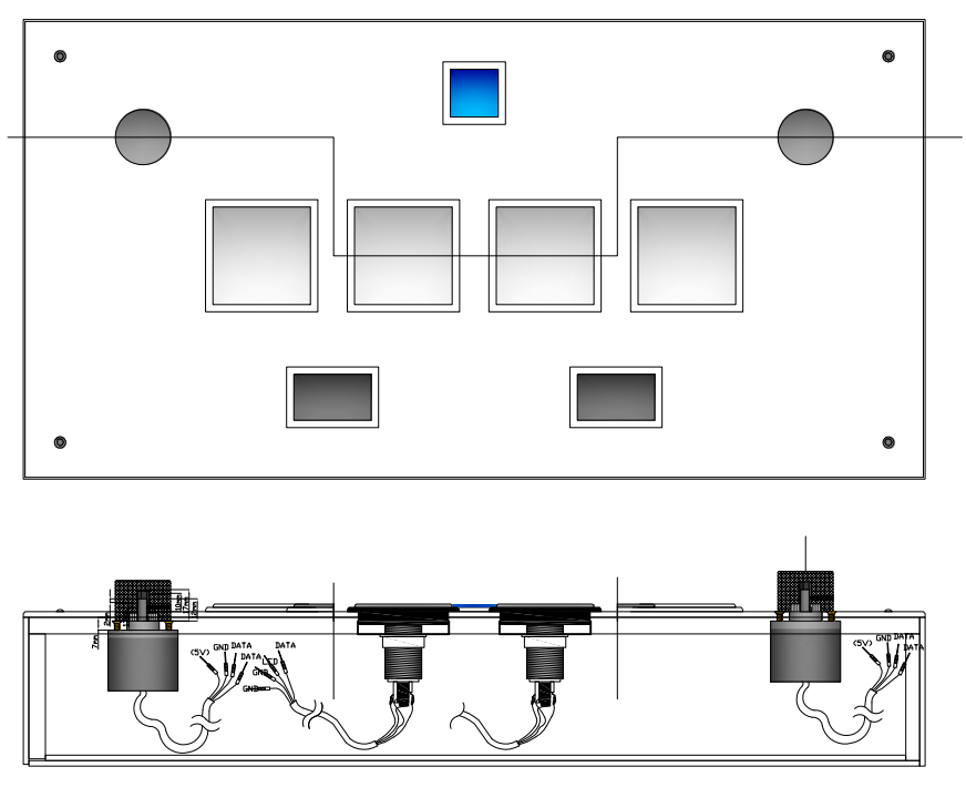
Buttons Assembly every button in its place on the acrylic board. Use the plastic nut to keep them in place. After that put the white plastic center in the button inserting it rotates 15° pushing and then locking it rotating it 15° back. Don't forget to add your printed vynil bellow the clear acrylic before inserting the buttons.
Encoders Mount the encoders using 3 small screws.
Crimp Connectors Use crimp connectors in each wire of the 7 molex wires your gonna use. You should en up with 7 wires, each with 4 crimp connectors (1 LED, 1 DATA and 2 GROUND), and also 2 other wires for the encoders (1 DATA A, 1 DATA B, 1 5v input and 1 GROUND).
Perfboard Following this drawing (drawing pending) solder each male molex connector in the perfboard. Then using PCB wires solder each molex pin with another molex pin (For the DATA and LED pins) and solder all the grounds in a single line.
Teensy Solder each corresponding molex wire to each hole in the PCB. You should end up with 3 6-pin wires.
Mount everything toghether connecting each molex wire to the perfboard and to the buttons.
If a button doesn't work, try checking the solder to see if its connected properly. Also check the ground connections.