This Arduino project creates a simple device that allows the user to test for continuity between two ends of an ethernet cable. In particular this device is made to test which ethernet port on a patch panel corresponds to a certain ethernet port on the wall of a home with internal Cat-5e wiring.
With the specific requirement of finding continuity rather than testing for a good connection this device may not suit everyone's needs. If you modify the project to suit a different use case let me know and I'll put a link to it in the readme.
- Take the looped ethernet cable and plug it into the wall socket that you are going to locate on the patch panel.
- Return to the patch panel and plug the ethernet cable that comes out of the device into all of the ports on the patch panel until a sound is made by the device.
- The sound represents that a loop has been found in the ethernet cable and that the port which you plugged the loop cable into in step 1 corresponds to this port on the patch panel. (Note that if there is a computer plugged into a wall socket then the device may also sound when plugged into the socket corresponding to the port that this computer is plugged into, so it is best to unplug all computers and devices from wall sockets before testing.)
- The lights on the device will also light up and show you which cores of the cable have a loop in them. Ideally all of the cores will have a loop in them and if not this could point to a fault. Note that the red led represents the brown core.
This project (for the specific use case detailed above) requires 2 rj45 (female) connectors with the wires exposed. I used a 0.5m cat-5e cable and cut it in half to achieve this.
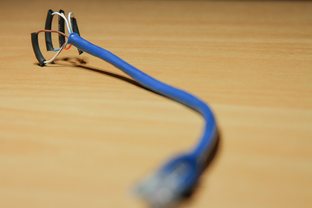
With one of the rj45 connectors take the exposed wires and join each of the solid colored wires to its corresponding banded colored wire. For example join the green wire to the green-white wire. I joined the wires by soldering them together and putting some heat shrink over the top of the soldered connection. This creates a loop and forms the cable that we will plug into the wall rj45 wall socket that we want to locate on the patch panel (see photo below).
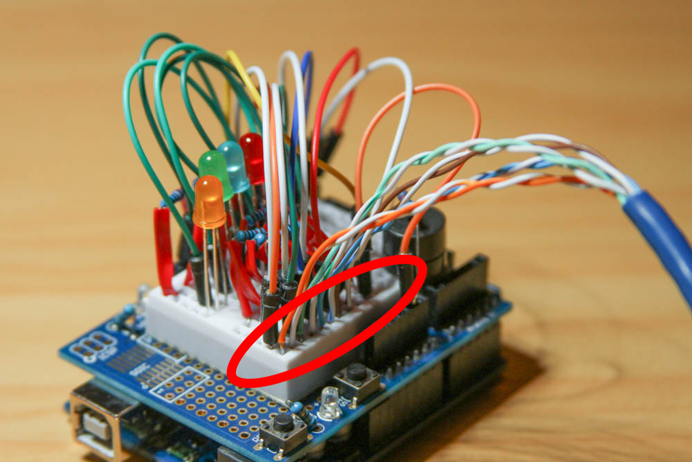
With the other half of the cat-5e cable we need to prepare the exposed wires to be plugged into a breadboard. I achieved this by stripping back each core individually and then by tinning each core.
Stripping and tinning the cores is not strictly necessary however this will ensure the the cores are able to easily be inserted into a breadboard. See the image below showing how the cores from this cable are inserted into a breadboard.
There's nothing too complicated in terms of wiring up this device, there's just a lot going on. Wire up your Arduino as shown in the diagram below.
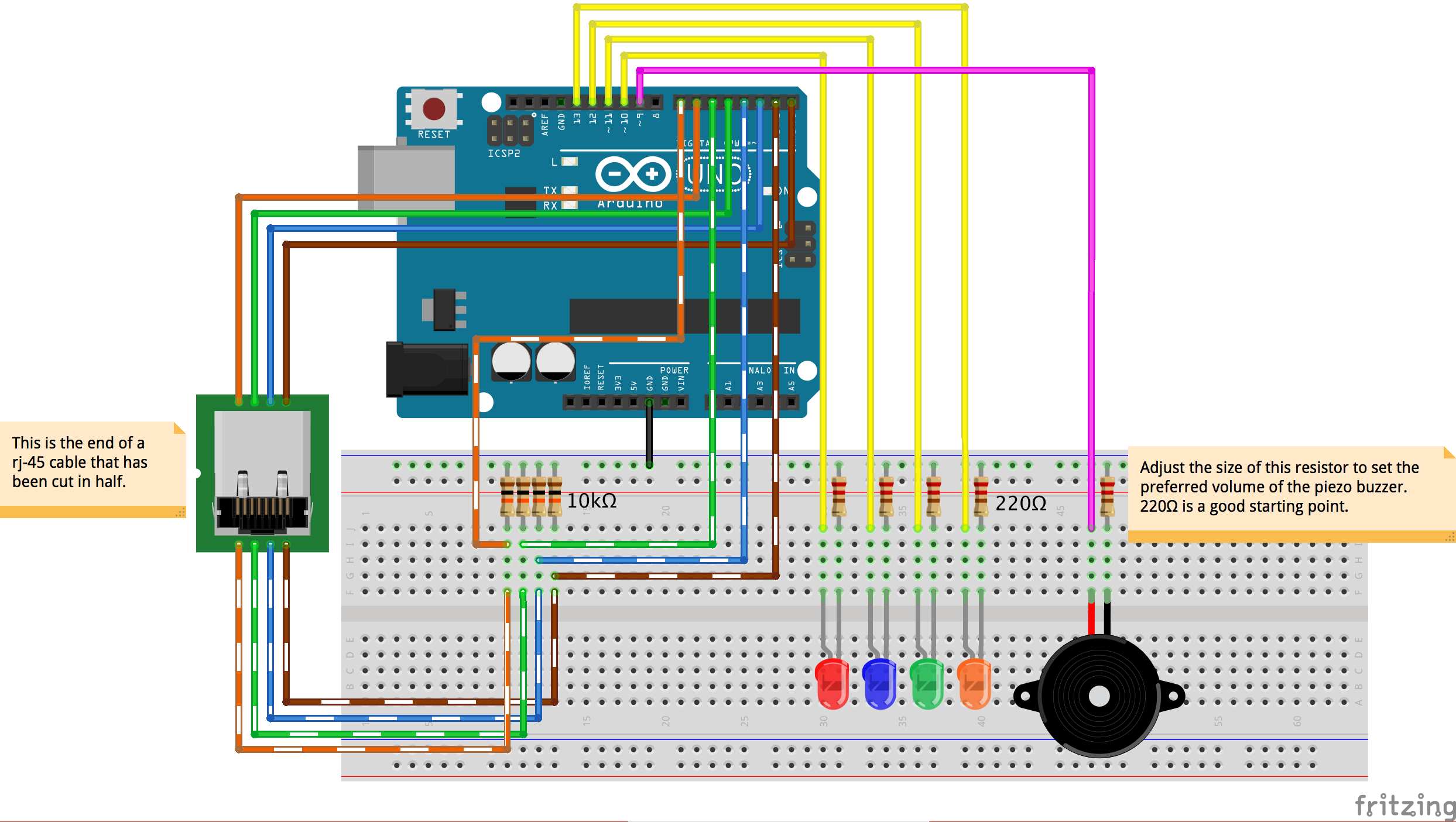
The code behind this project is also pretty simple. Upload the code in the Ethernet_Continuity_Tester.ino sketch to the Arduino Uno and provided you wired everything up correctly you shouldn't have to change anything.
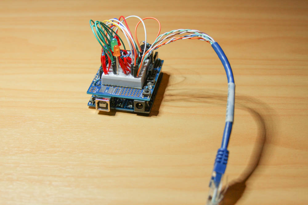
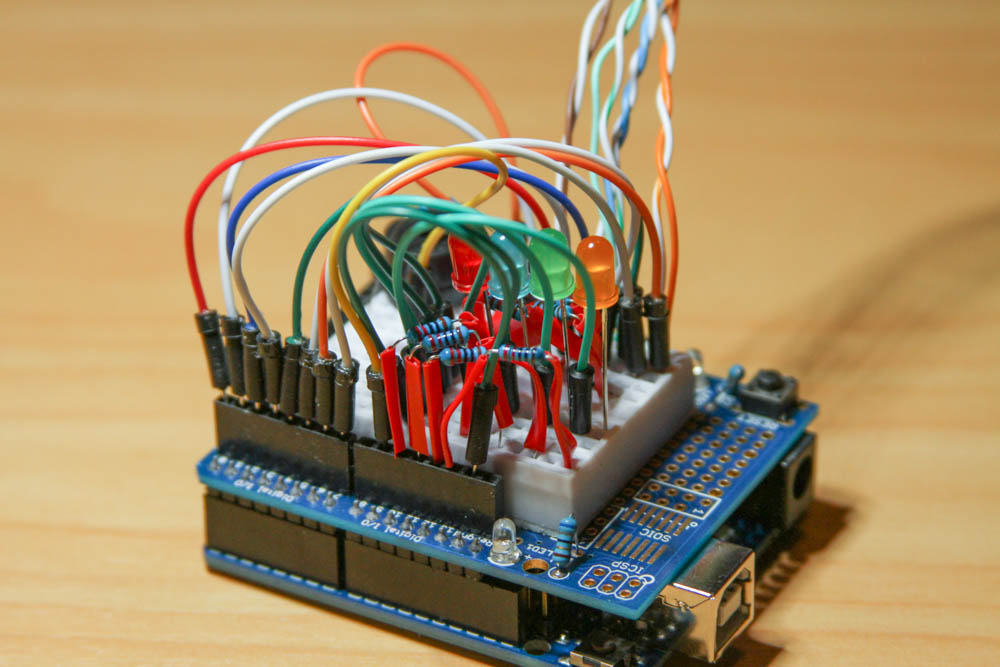
To keep the device itself compact I built all of this on a prototyping board with a miniature breadboard attached. Here are some photos of the finished device.