Modbus Wiring Guide
On the bottom of your FoxESS H1 inverter is a large connector.
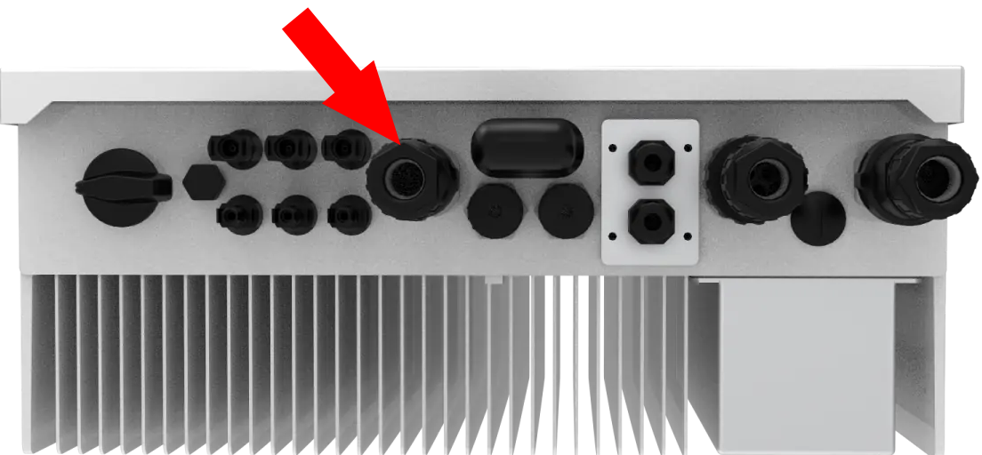
Other model inverters have a different connector layout, so check your manual. You are looking for the connector marked Meter/CT/RS485.
The connector has many smaller pins inside of it. Two of the pins are for the Meter or CT clamp, which should already be attached. Two of the remaining pins are for an RS485 connection, which lets you communicate directly with the inverter using Modbus. If you wire these pins to a Modbus to USB or Modbus to Ethernet adapter, this lets Home Assistant fetch data from your inverter, and even write some settings back to it.
This method of connection to your inverter is more powerful than Connecting a LAN cable: there are some registers which are only available over RS485 (mainly around the BMS, and agent settings), and you can also write configuration settings back to the inverter, to change things like the Min/Max SoC, Work Mode, and charge periods. However, it's a little bit more fiddly and you'll have to spend a bit of money on an adapter.
On the front panel of the inverter, go to Settings -> Communication -> RS485 -> Device ID and check the slave ID for the inverter is set to 247 (H3, for example, defaults to 000). The default password is "0000".
You'll need a Modbus to Ethernet/WiFi or Modbus to USB adapter, see the links in the sidebar to the right for some suggestions. You're welcome to use others, provided that they use the correct RS485 (not RS232) voltages.
You'll also need some cabling to connect your adapter to your inverter. Twisted pair works best for long runs, and many people use a length of CAT5 ethernet cable, taking one of a twisted pair for the A connection, and its partner for the B connection. Be aware however that CAT5 can be brittle and might snap around the grub screws. For short runs (a meter or two) even a length of cheap speaker cable will do.
You'll also want a screwdriver set.
First, turn off your inverter:
NOTE: Turning off the inverter might cause some settings to get lost! On powering back on, if there are no error messages and status is 'Normal' but the inverter does not supply power, ensure the Meter/CT setting has not been lost (video): Using the menus, Settings -> Feature -> Meter/CT - make sure it's set to CT if you have a CT clamp, or Meter if you have a CHINT meter and is not set to Disable.
- If your installer put a switch on the cables from your solar panels, turn this off. Otherwise, on the bottom left of your inverter is a switch to turn off the solar input: turn this until it clicks.
- If you have batteries, turn off the BMS: press the power button then flip the circuit breakers off (to the left)
- Turn off the AC / grid isolator, which should be clearly marked and located between your inverter and your main consumer board.
- Wait for 10 seconds and check the inverter has powered down and the front panel screen is dark.
See the video by William Eccles here:

Disconnect the Meter/CT/RS485 connector shown in the image at the top of this page. There's a clip on each side which you can push in, and it should pop off. Make sure that you don't pull on the existing Meter/CT cable as it might come out.
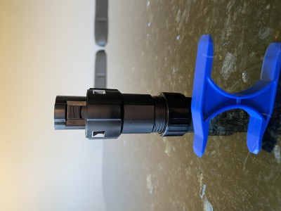
Next, you need to disassemble it. Your installer may have left behind a small blue H-shaped tool: slip two of the arms into the two slots on the body of the connector, which will push down on two little clips and let it open up. If you don't have this tool, you can use a pair of flathead screwdrivers, or if you are fortunate enough to have access to a 3D printer can print yourself your very own H-shaped tool using this model.


This step depends on whether you've got a H1 or H3 inverter. Check the manual which came with your inverter to be sure, in case yours is different.
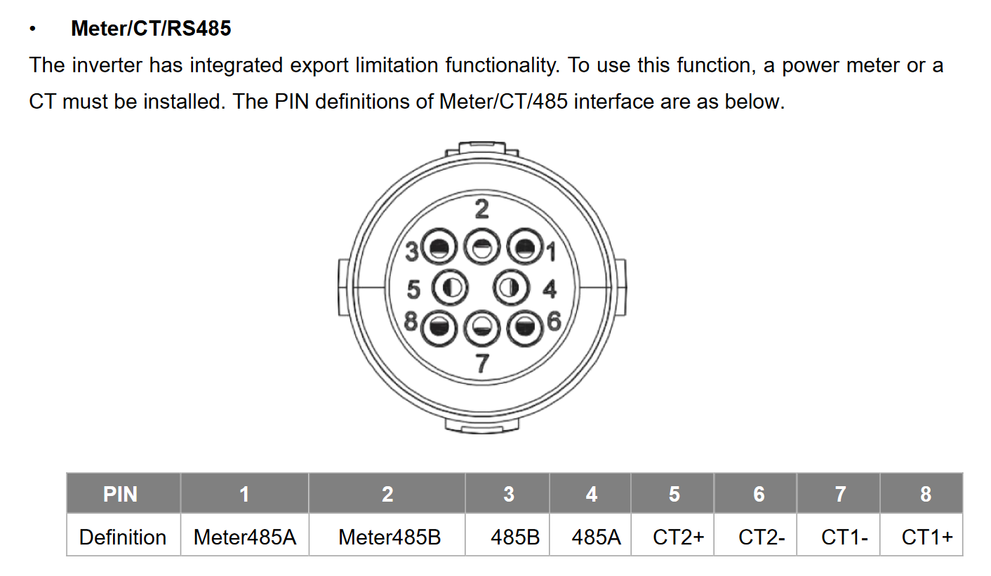
For the H1, you'll want to connect one wire to the "485A" connection (pin 4), and another to the "485B" connection (pin 3). Make sure you remember which is which, as you'll need to connect them the right way around to your adapter!
There are little grub screws on the sides of the pins.
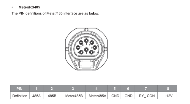
For the H3, you'll want to connect one wire to the "485A" connection (pin 1), and another to the "485B" connection (pin 2). These might also be called "Logger 485A" and "Logger 485B". Do not connect to "Meter 485A/B". Make sure you remember which is which, as you'll need to connect them the right way around to your adapter!
There are little grub screws on the sides of the pins.
Example wiring for H1 below. Please note the poor wiring from the original installer (pin 8) for the CT clamp - if any of your pin connections need adjusting, now is the time to do it.

Connect the other ends of the wires to your adapter. Make sure you get them the right way around, see the pages linked in the sidebar for more info.
Reassemble the clamp, and connect it back to your inverter, then power the inverter on:
- Turn the AC / grid isolator back on
- Flip the DC breaker on the BMS to the right, then press the BMS power button
- Turn on the DC side of the inverter, doing the opposite of what you did to turn it off
The inverter will power up. Check for any faults, check the Meter/CT and RS485 slave ID settings (described above) and Start the inverter. It will run through a 60 second check sequence and then go into normal operating mode. Check the grid and load power shown in the app to confirm the Meter or CT clamp are operating as expected.