Quantum Gate Nodes

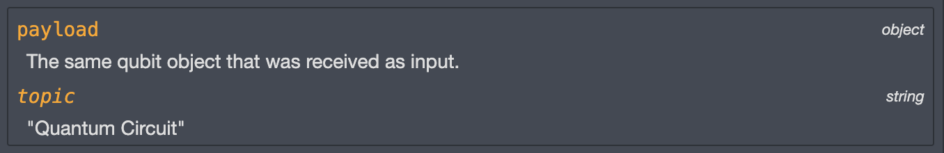
This node applies the identity gate to the input qubit.
The identity gate corresponds to a null operation.
It does not affect the state of the qubit.

Identity gate - Qiskit textbook
Identity gate - Qiskit documentation

Also called the X gate, this node inverses the qubit state: 0 → 1 & 1 → 0.
In terms of the Bloch Sphere, this corresponds to a reflection of the sphere along the x-axis.

NOT gate - Qiskit textbook
NOT gate - Qiskit documentation

This node rotates the input qubit by a given angle about the x, y or z axis.
To do so, open the node properties, select the rotation axis &
drag the slider to specify the angle of rotation (in radians).
In terms of the Bloch Sphere, this corresponds to a rotation of the sphere along the specified axis.
X-axis rotation - Qiskit documentation
Y-axis rotation - Qiskit documentation
Z-axis rotation - Qiskit documentation

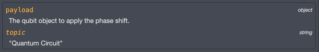
This node allows you to apply a phase of eiλ to the input qubit.
To do this, open the node properties & drag the slider to specify the angle λ (in radians)
by which you would like to shift the input qubit phase.
A phase shift correspond to adding a factor eiλ in front of the '1' state of the qubit.
If the qubit is in a superposition state, only the '1' state is affected by the phase.
In terms of the Bloch Sphere representation, this corresponds to a rotation of λ radians around the z-axis.
However, in terms of qubit state, a phase shift differs from a z-rotation by a global phase of eiλ/2.

Phase gate - Qiskit textbook
Phase gate - Qiskit documentation

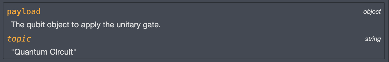
This node applies the unitary (U) quantum gate to the input qubit.
It is the most general single qubit gate, it can apply any rotation and a phase shift.
To do so, open the node properties and use the sliders to set the values of the 3 gate parameters:
- Theta (θ): the rotation angle in radians along the y-axis
- Phi (φ): the rotation angle in radians along the z-axis
- Lambda (λ): the angle in radians for the phase shift
In terms of the Bloch Sphere, this corresponds to rotations around the y and z-axis along with a phase shift.
Unitary gate - Qiskit textbook
Unitary gate - Qiskit documentation
This node allows you to apply the Hadamard gate.
The Hadamard is mostly used to change a qubit from the '0' or '1' state to an equiprobable superposition of the 2 states (50% '0' / 50% '1').
Applying the hadamard gate to a qubit in the '0' state will put it in
the Bloch Sphere state at the intersection with the positive x-axis, known as |+> state.
Applying it to a qubit in the '1' state will put it in the Bloch Sphere state
at the intersection with the negative x-axis, known as |-> state.
In terms of the Bloch Sphere, this corresponds to
a π/2 radians rotation of the sphere along the line in between the x and
z-axis (ex + ez).
The Hadamard operator being an unitary matrix, applying two successive
Hadamard gates to the same qubit leaves the qubit in his original state.

Hadamard gate - Qiskit textbook
Hadamard gate - Qiskit documentation

This node allows you to apply a NOT gate to a 'target' qubit if the 'control' qubit is in the '1' state.
The NOT gate inverses the qubit state: 0 → 1 / 1 → 0.
To do this, connect two qubits as input and indicate whether the
target is the visually upper or visually lower qubit, out of the two input qubits.
In terms of the Bloch Sphere,
this corresponds to a reflection of the sphere along the x-axis of the 'target' qubit.
The 'control' qubit state is not affected.
Now, let's assume the 'target' qubit is in the '0' state.
If the 'control' qubit is in a superposition state (25% '0' / 75% '1'),
then the combined state of the 2 qubits will be:
- '00' with 25% probability
- '11' with 75% probability
Entanglement - Qiskit textbook
CNOT gate - Qiskit textbook
CNOT gate - Qiskit documentation

This node allows you to apply a NOT gate to a 'target' qubit if the 2 'control' qubits are in the '1' state.
The NOT gate inverses the qubit state: 0 → 1 / 1 → 0.
To do this, connect three qubits as input and indicate the visual position (top, middle or bottom)
of the 'target' qubit among the connected qubits.
In terms of the Bloch Sphere,
this corresponds to a reflection of the sphere along the x-axis of the 'target' qubit.
The 'control' qubits states are not affected.
Now, let's assume the 'target' qubit in the '0' state.
If the 2 'control' qubits that are in the same superposition state (50% '0' / 50% '1'),
then the combined state of the 3 qubits will be:
- '00 0' with 25% probability
- '01 0' with 25% probability
- '10 0' with 25% probability
- '11 1' with 25% probability
Entanglement - Qiskit textbook
TOFFOLI gate - Qiskit textbook
TOFFOLI gate - Qiskit documentation

This node allows you to apply a unitary (U) gate to a 'target' qubit if the 'control' qubit is in the '1' state.
The CU gate is the most general 2-qubits gate, it can apply any rotation, a phase shift and a global phase.
To do this, connect two qubits as input and indicate whether the
target is the visually upper or visually lower qubit, out of the two input qubits.
Then, use the sliders to set the values of the 4 gate parameters:
- Theta (θ): the rotation angle in radians along the y-axis
- Phi (φ): the rotation angle in radians along the z-axis
- Lambda (λ): the angle in radians for the phase shift
- Gamma (γ): the angle in radians for the global phase
A global phase correspond to adding a factor eiγ in front of the overall qubit state. If the qubit is in a superposition state, both the '0' and '1' states of the qubit are affected by the global phase.
In terms of the Bloch Sphere, this corresponds to rotations around the y and z-axis along with a global phase and a phase shift of the 'target' qubit. The 'control' qubit state is not affected.
Now, let's assume we apply a U(π,0,0) gate to a 'target' qubit in the '0' state. In this case the U gate is equivalent to a NOT gate (0 → 1 & 1 → 0).
If the 'control' qubit is in a superposition state (25% '0' / 75% '1'), then the combined state of the 2 qubits will be:
- '00' with 25% probability
- '11' with 75% probability
Entanglement - Qiskit textbook
CU gate - Qiskit documentation
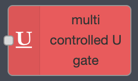
This node allows you to apply a unitary (U) gate to a 'target' qubit if all 'control' qubits are in the '1' state.
The MCU gate is the most general multi qubits gate, it can apply any rotation and a phase shift.
To do this, open the node properties and enter the number of 'control' qubits.
Connect the 'control' qubits and one 'target' qubit as inputs.
Indicate the visual rank (higher, second higher ...) of the 'target' qubit among the connected qubits.
Then, use the sliders to set the values of the 3 gate parameters:
- Theta (θ): the rotation angle in radians along the y-axis
- Phi (φ): the rotation angle in radians along the z-axis
- Lambda (λ): the angle in radians for the phase shift
In terms of the Bloch Sphere, this corresponds to rotations around the y and z-axis along with a phase shift of the 'target' qubit. The 'control' qubits states are not affected.
Now, let's assume we apply a U(π,0,0) gate to a 'target' qubit in the '0' state. In this case the U gate is equivalent to a NOT gate (0 → 1 & 1 → 0).
Let's assume that we are using 2 'control' qubits that are in the same superposition state (50% '0' / 50% '1'). Then the combined state of the 3 qubits will be:
- '00 0' with 25% probability
- '01 0' with 25% probability
- '10 0' with 25% probability
- '11 1' with 25% probability
Entanglement - Qiskit textbook

Unitary gate - Qiskit textbook
Unitary gate - Qiskit documentation