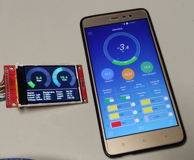
This project provides Platform.io code for building an STM32F103C8T6 "blue pill" based monitor for a JBD BMS.
- Sends read commands to the JBD BMS and receives all key statistics, including battery voltage, current, remaining capacity, number of cycles, BMS protection status, state of charge, NTC temperatures, individual cell voltages and cell delta voltage.
- Prints these statistics to the Serial1 (PA9 and PA10) output and also displays key metrics on a TFT screen.
- Allows simultaneous operation with the stock Bluetooth dongle over the single UART interface on the BMS.
- Turns an optional external active cell balancer (e.g. Hankzor) on and off when certain cell voltage thresholds are met (by default it will turn on when any cell is above 3.4v, and off when the highest cell drops below 3.35v).
- A generic 3.3v 320x240 ILI9341 TFT screen can be connected through the STM32's SPI interface to display realtime statistics.
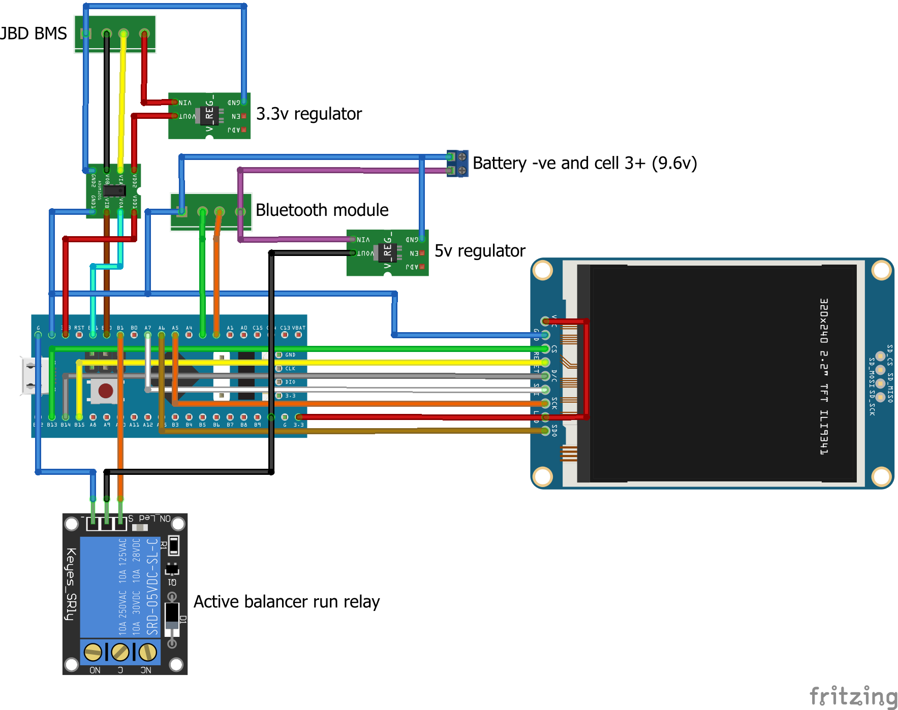
- To avoid ground loops, it is essential to use an ADUM1201 serial isolator between the BMS UART interface and the STM32.
- The active-high input for a relay connected across the balancer's "run" pads should be connected to PB1.
- The variables maxCurrent, minVoltage and maxVoltage should be adjusted in the code to suit your battery to ensure the ring meters render with a useful scale.
- The STM32 can operate without the TFT display attached. Remove the TFT_ENABLE define to disable all TFT functions.
- The TFT_eSPI library must be configured to suit your display. For the generic SPI ILI9341:
- Edit .pio\libdeps\bluepill_f103c8\TFT_eSPI\User_Setups\Setup32_ILI9341_STM32F103.h lines 24, 25 and 26 as below:
- #define TFT_CS PB13 // Chip select control pin to TFT CS
- #define TFT_DC PB14 // Data Command control pin to TFT DC (may be labelled RS = Register Select)
- #define TFT_RST PB15 // Reset pin to TFT RST (or RESET)
- Remove the two slashes at the start of line 70 in .pio\libdeps\bluepill_f103c8\TFT_eSPI\User_Setup_Select.h as below:
- #include <User_Setups/Setup32_ILI9341_STM32F103.h> // Setup for "Blue/Black Pill"
- Edit .pio\libdeps\bluepill_f103c8\TFT_eSPI\User_Setups\Setup32_ILI9341_STM32F103.h lines 24, 25 and 26 as below:
- If you need more advanced functinality including the ability to send statistics to InfluxDB over WiFi, have a look at the sister project for the ESP8266 here: https://github.com/octal-ip/ESP8266_JBD_BMS_Monitor
- STM32F103 "blue pill" board (or clone)
- ST-Link v2 programmer (only if you don't have one already)
- ADUM1201 dual channel digital isolator
- 2 x linear voltage regulator modules, one 3.3v and one 5v.
- 5v relay module
- ILI9341 SPI TFT screen (optional, but very useful - must be the 3.3v version)
| STM32 Pin | ILI9341 TFT Pin |
|---|---|
| PB13 | CS |
| PB14 | DC |
| PB15 | RST |
| PA7 | MOSI |
| PA6 | MISO |
| PA5 | SCK |
| +3.3v | LED |
| ADUM1201 Pin | STM32 Pin | JBD BMS Pin |
|---|---|---|
| VIA | X | TX (next to positive) |
| VIB | TX3 (PB10) | X |
| VOA | RX3 (PB11) | X |
| VOB | X | RX (next to negative) |
| VDD1 | 3.3v | X |
| GND1 | GND | X |
| VDD2 | X | Positive via 3.3v regulator (red) |
| GND2 | X | Negative (black) |
| Bluetooth Pin | STM32 Pin |
|---|---|
| TXD | TX2 (PA2) |
| RXD | RX2 (PA3) |
| GND | GND |
| VCC | Battery cell 3 +ve (~10v) |

