Problem Display 64128COG - Driver KS0713 #1105
Comments
|
Maybe the display power lines are missing? |
|
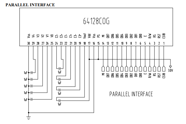
The connections I am using are those defined in your datasheet. I have tried both Serial and Parallel conumication. Thank you so much for everything |

|
The idea is this: You need to check your wiring. Sending datasheet diagrams does not really help here. For example you mention, that Reset is connected to D8. This information alone will not help to validate your setup. You also need to mention where you have connected D8. So a proper connection would at least be this: Maybe you can provide this connection for the remaining pins (just to check, that all is planned corretly). Then you could make a screenshot of your wiring and we can crosscheck your wiring together. |
Nice, but if you want me to support here, you need to tell me how the pins from your display are connected? For example: To which Arduino Mega pin is RS connected? |
|
if I haven't understood it wrong, these are the Pin's should connect. U8g2 Constructor Argument|Pin Display | Pin Arduino Mega | CS | CS1B | Pin 10 | Reset | RST | Pin 8 | DC | RS | Pin 9 | DATA | SID(DB7) | Pin 51 | CLOCK | SCLK(DB6)| Pin 52 | Other Pin | MI | VCC | | PS | GND | | VCC | 3.3V | | GND | GND | Thank you |
|
Looks good from u8g2 perspective. Is your pcb correct? How is the PCB connected to Arduino? |
Hmm.. you always tell me that you did everything correctly. I wonder why you need my help. So this is my last suggestion: Make a list of things what could be wrong. This list can be easily 20 to 30 line items. Do not think that things are correct. Be open. Do not assume anything. Then you need to prove that all thinks are correct. One question could be this: Did I use the correct capacitors? Is the type correct? is value correct? |
|
It was not my intention to offend, only when I say that everything is correct, I followed the datasheet scheme for PCB creation. I know something must fail, that's why I'm consulting you. I assume that I am not as expert as you are on the subject, so I want to be advised by you. All the information I have right now about it, is what I have currently provided. He just wanted to know if he could come up with a solution. It was also to know if the constructor that I am using was suitable for said screen, since I am using one that suits the driver that has said display. |
|
I have just assembled the circuit again and I have been measuring with a polymeter the voltage that reaches the LCD, I have observed that when I have removed the VCC cable, it continues to reach the 3.3V LCD. |
Are you sure there is a backlight? There might be no backlight. It sometimes has to be mounted separatly.
Try the contrast demo of u8g2. It will loop over all possible contrast value. It might be the case, that you display requires a different contrast: I mean, the default contrast value may not fit for your display. |
|
Right now I have checked what he has told me and what I have discovered has killed me. In the Pin Vout that is connected to the capacitors, if I am not mistaken it is for the power supply of the screen. This voltage must be between 9V to 11V. Sometimes if you get that voltage but another stays in the circuit input voltage and the screen goes black but most of the time it is blank. Could it be that some capacitor is not working properly? |
|
Oh, i missed your last reply. |
Hi, I have a problem with this display adapter to the library.
I am connecting the display via SPI, with the "ST7565 64128N" constructor. I get nothing, not even to backlight.
Conexiones:
Arduino mega 2560
Reset= D8
DC=D9
CS=D10
SID=D51
SCLK=D52
Thank you
The text was updated successfully, but these errors were encountered: