Pi With Slice of Radio
The Slice of Radio device uses the same core chip as the ERF stick. You can follow most of the instructions from Intel-Edison-with-ERF-stick and Writing-Firmware-to-the-ERF-stick.
Jessie:
sudo systemctl stop serial-getty@ttyAMA0.servicesudo systemctl disable serial-getty@ttyAMA0.service-
sudo nano /boot/cmdline.txtand remove the sections referring to ttyAMA0 as per the below link. Note that with the most recent raspberry pi release the string to be removed isconsole=serial0,115200 -
sudo shutdown -r nowto make sure that nothing is using the serial port -
sudo apt-get install rpi-updateandsudo rpi-updateto update the Pi firmware -
sudo nano /boot/config.txtand go to the bottom and changeenable_uart=0toenable_uart=1
The original instructions are at http://www.hobbytronics.co.uk/raspberry-pi-serial-port Note If you're running the latest version of the Raspbian (Jessie), the file /etc/inittab has been replaced, and you should use the commands above.
Wheezy:
-
sudo nano /etc/inittaband comment the ttyAMA0 line as per the above link -
sudo nano /boot/cmdline.txtand remove the sections referring to ttyAMA0 as per the above link -
sudo shutdown -r nowto make sure that nothing is using the serial port
NOTE - Doing this invalidates your Ciseco/WirelessThings warranty
Don't be alarmed by dim LEDs on the board - once you've written the firmware, all the LEDs will turn on, but glow less brightly than they did before. This doesn't indicate a failure or that you've burned out the board - so don't panic!
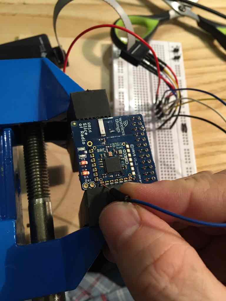
The instructions here are the same as Writing-Firmware-to-the-ERF-stick, with two exceptions.
- The grabber-style 'test hooks' won't clip onto the Slice of Radio - so you'd need to hold connectors manually.
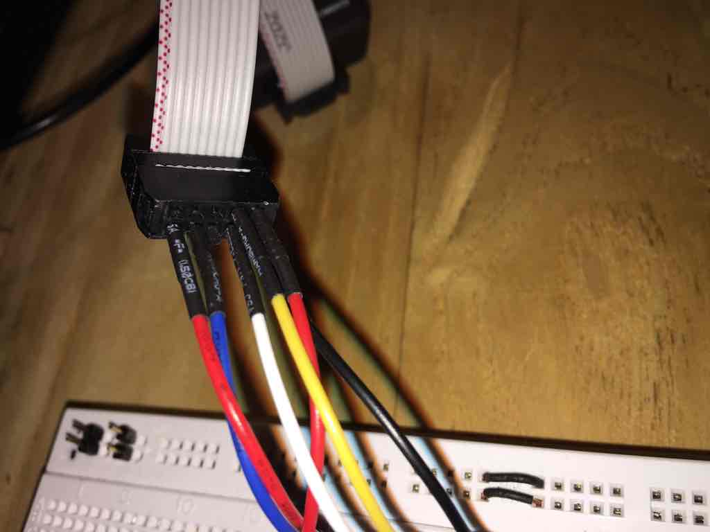
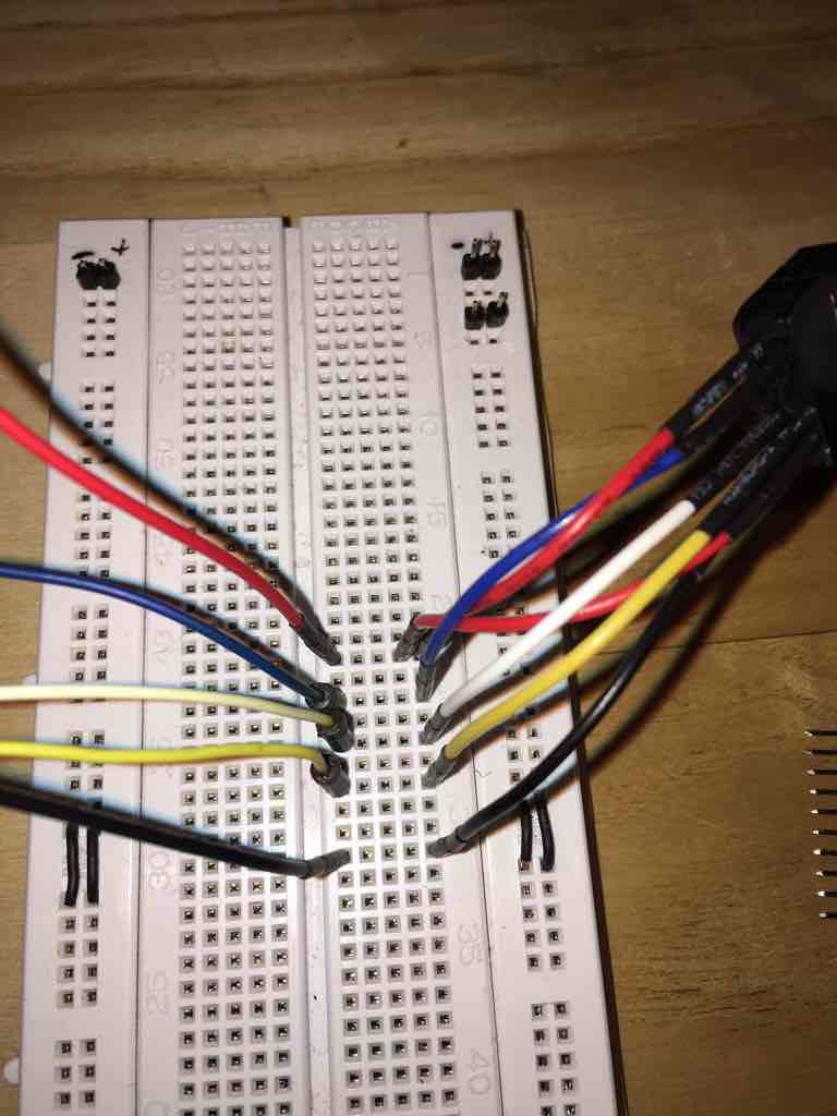
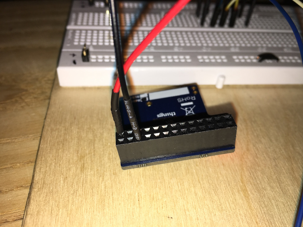
- To connect the power pins, plug the connectors in as follows:
Mapping from the CC-debugger to the relevant wires:
- These should be the same as on the ERF stick link above.
- The breadboard is simply for consistency with the ERF stick. You can avoid the breadboard entirely if you want - jumping straight from the CC-debugger connector to the slice of radio
Now for the core part of the process: you need to hold the white, yellow, and blue wires on these points at the same time, and have someone write the firmware at the same time. I couldn't take photos of this, as I only had two hands!
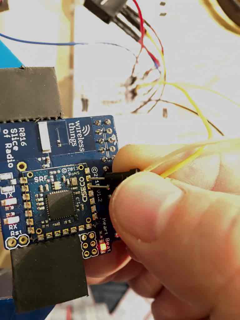
 While holding the wires in place:
- Press the little button on the CC-debugger. If you've got the wires in the right place, and they are making contact correctly, the Light on the cc-debugger will change from red to green
- Write the firmware with either cc-debugger or using the Texas Instruments firmware. The command for this is something like 'sudo cc-tool --log install.log -ew PATH-TO-YOUR-HEX-FILE.hex' (where the hex file is the latest release from https://github.com/ps2/subg_rfspy/releases - something like uart0_alt1_SRF_ERF_US_STDLOC.hex or uart0_alt1_SRF_ERF_WW_STDLOC.hex )
Note that if you want, you can run "sleep 30 ; sudo cc-tool --log install.log -ew PATH-TO-YOUR-HEX-FILE.hex" - and the system will wait for 30 seconds before running the cc-tool command. That should give you enough time to get the wires in the right place and press the button on the CC-debugger.
- The port that you'll need to use is /dev/ttyAMA0 instead of /dev/ttyMFD1 or /dev/ttyUSB0. Note that with Pi3 you may need to use /dev/ttyS0 if /dev/ttyAMA0 gives you errors.
- The instructions at Installing-MMeowlink should otherwise work
Adding an external antenna will not have a dramatic effect on performance, but will extend the working range by a few meters (sometimes this is what you really need). There are multiple options for antenna styles including a simple wire whip antenna or small self contained antenna.
-
u.FL to SMA female pigtail, something like this
-
u.FL SMD PCB connector, like this
-
Antenna itself, like this
-
8.2 cm of decent quality small wire (for wire whip antenna)
When buying, pay attention to male/female connectors - there are pigtails for male and female connectors, sometime in the description you will not see if it is male or female. Antennas mostly have male connectors. When buying u.FL connectors, buy more than one as they are so small that you can easily lose some of them. They are cheap, so buy 3-5 just to be sure. As for the antenna, look for 868MHz(EU) or 915MHz(US) antennas. The longer the antenna the better signal gain you'll get. But don't expect miracles.
You can find connector pads picture here (last picture). Use a tiny soldering iron as pieces are small.
For a wire whip antenna there is a connector hole in most boards for the placement, strip one end of the wire and insert it into the hole and solder it on.
After soldering the connector you'll need to cut off 2 components to eliminate on-chip antenna from the board. (see photos).
For plastic cases you can make a hole with a hot nail or screw. SMA part of pigtail has a nut that you can use to fix the connector on the plastic case.
No software modifications needed. But to evaluate the solution you should make some measurements before and after mounting the antenna. You can run 'mmtune' several times, having pi and the pump in different places and record the results.