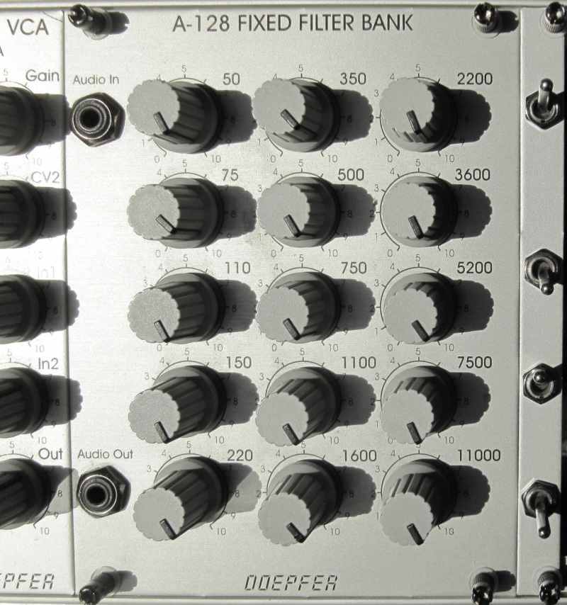
Extending the Doepfer A-128 fixed filter bank eurorack module with 4 bypass switches.
If you are the owner of a Doepfer A-128 fixed filter bank this project might be useful for you.
With a few bucks for material and 1 hour of work you can create an extension module that adds bypass functionality to your filter bank.
- Switch 1: bypass the whole filter module and send the incoming signal directly to the output
- Switch 2: mute all high frequencies (greater ~1500 Hz)
- Switch 3: mute all mid frequencies (~200 - 1500 Hz)
- Switch 4: mute all low frequencies (below ~200 Hz)

Yes, simply place 4 jumpers in the breakout connector. The signal flow will be exactly the same like without the mod.

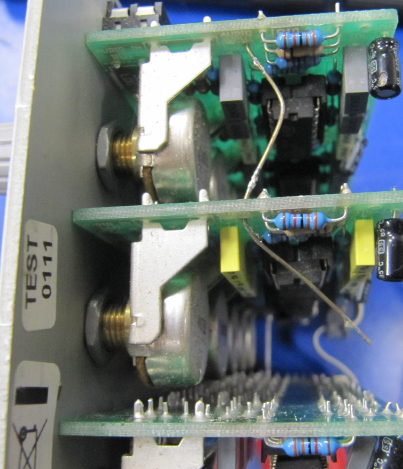
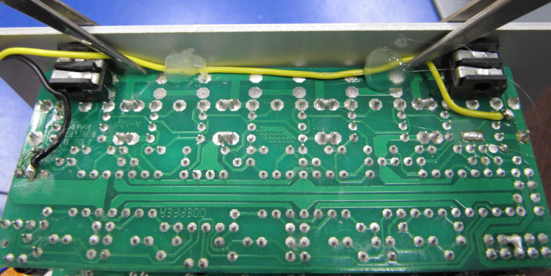
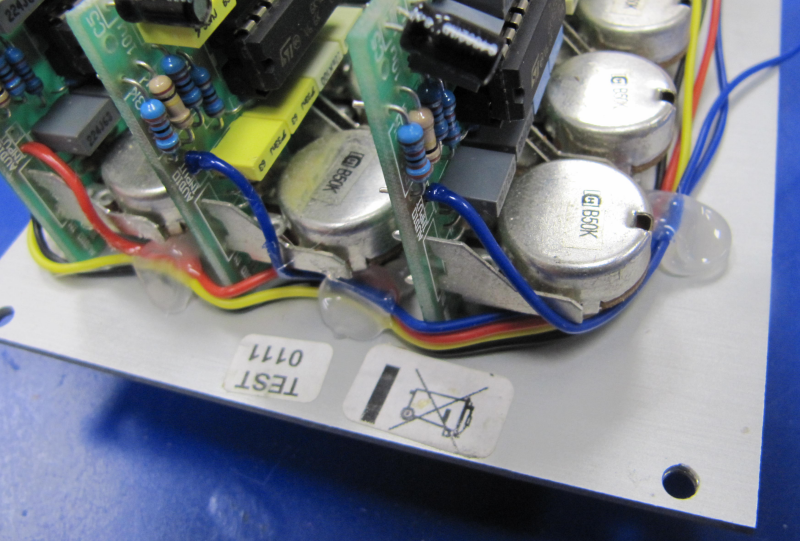
Find and desolder the wire on the upper half of the module that connects the 3 PCB's with label AUDIO INPUT.
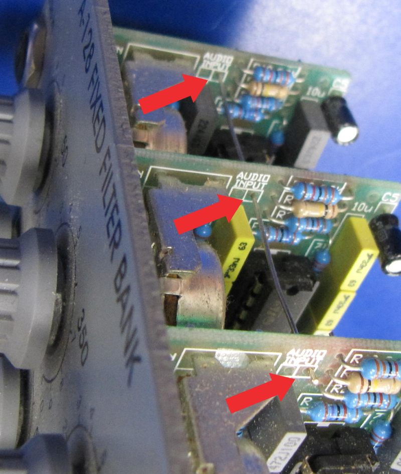
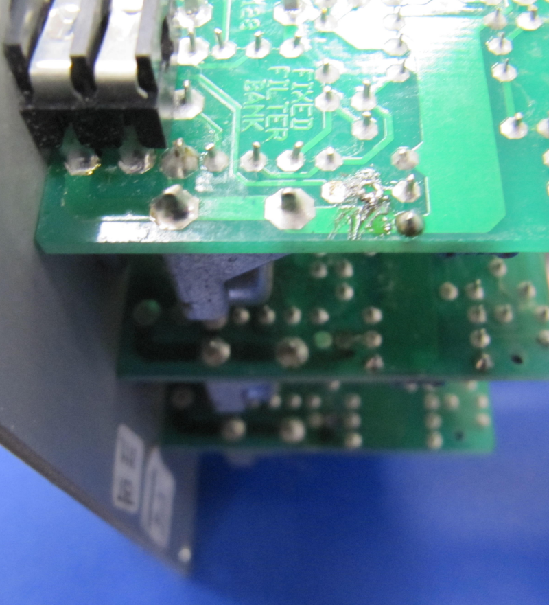
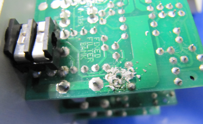
Drill a 1.5mm hole into left PCB (with in-/output jacks and potentiometers for low frequencies) where you desoldered the AUDIO INPUT wire.
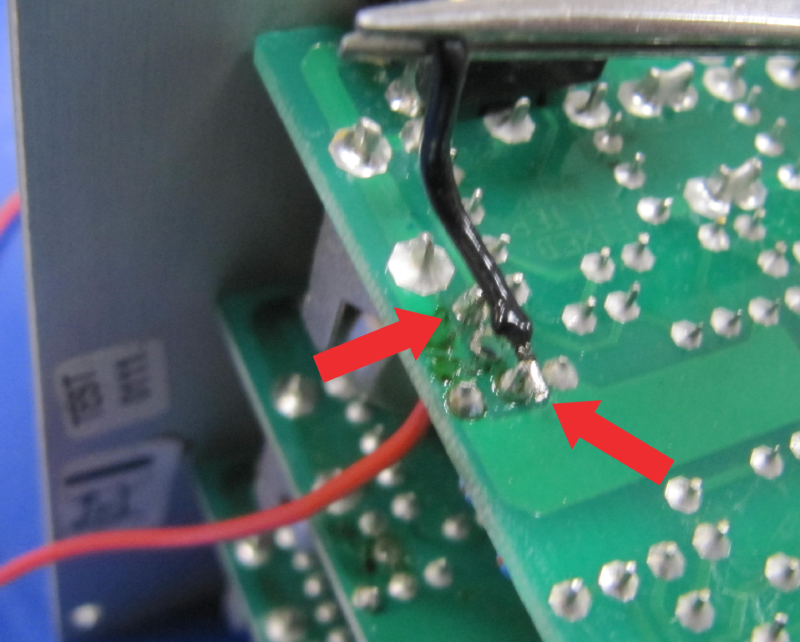
Ensure that there is no connectivity between the pins shown in the picture below.
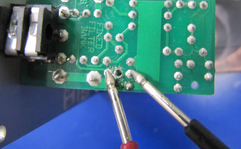
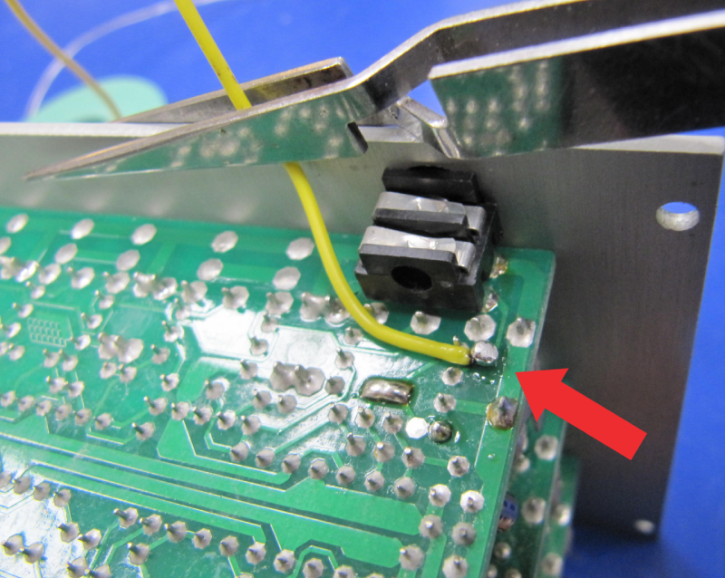
Solder 2 wires into the connection points next to the drilled hole.
I used a red wire for AUDIO INPUT which has connectivity to the tip of the input jack and a black wire which is the audio input for the low frequencies circuit.
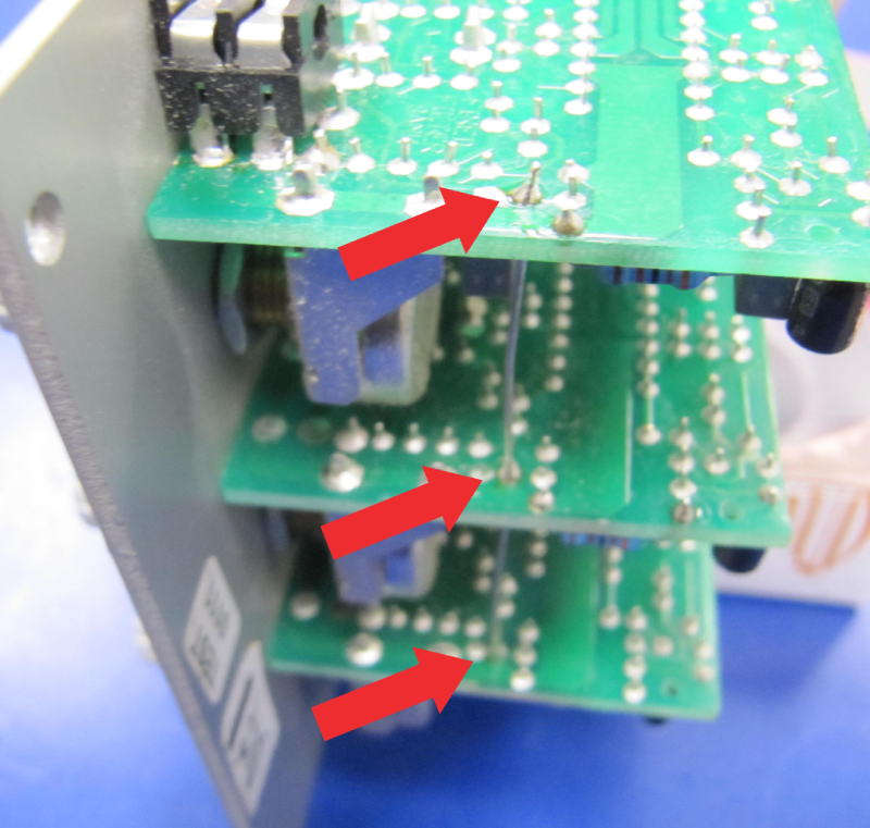
Solder another wire next to the OUTPUT-jack.
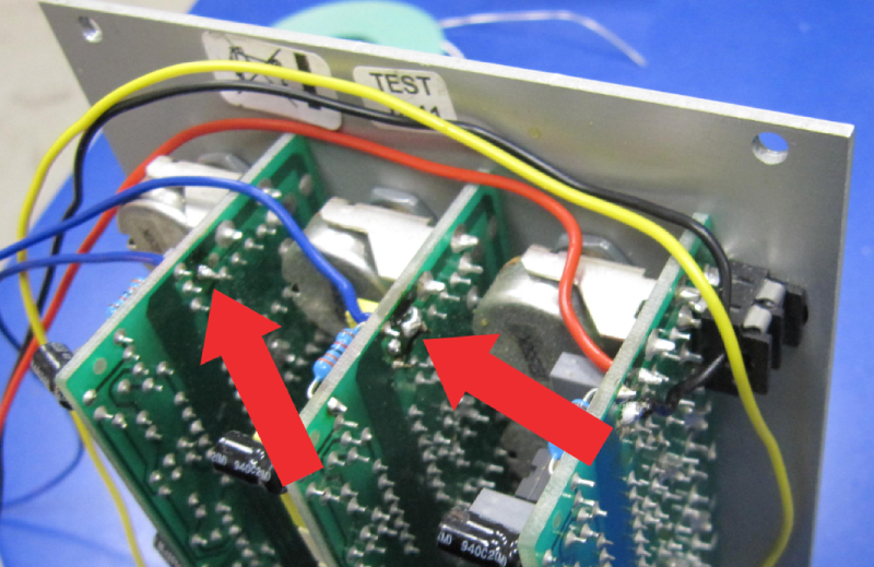
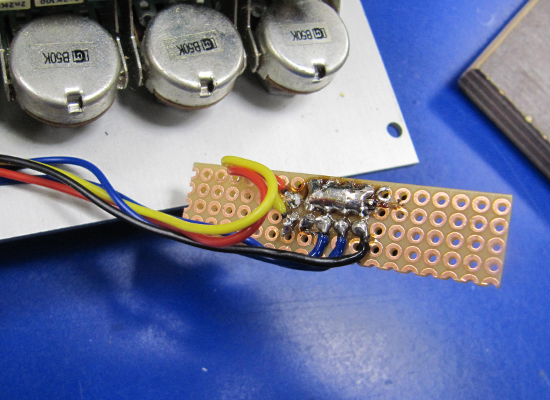
Solder 2 wires into the holes where you removed the AUDIO INPUT connection wire in step 1 on PCB2 and PCB3
Hot glue is your friend
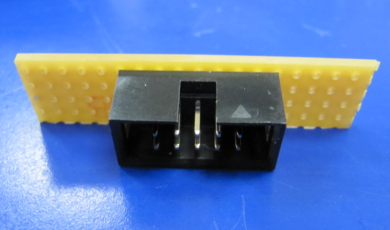
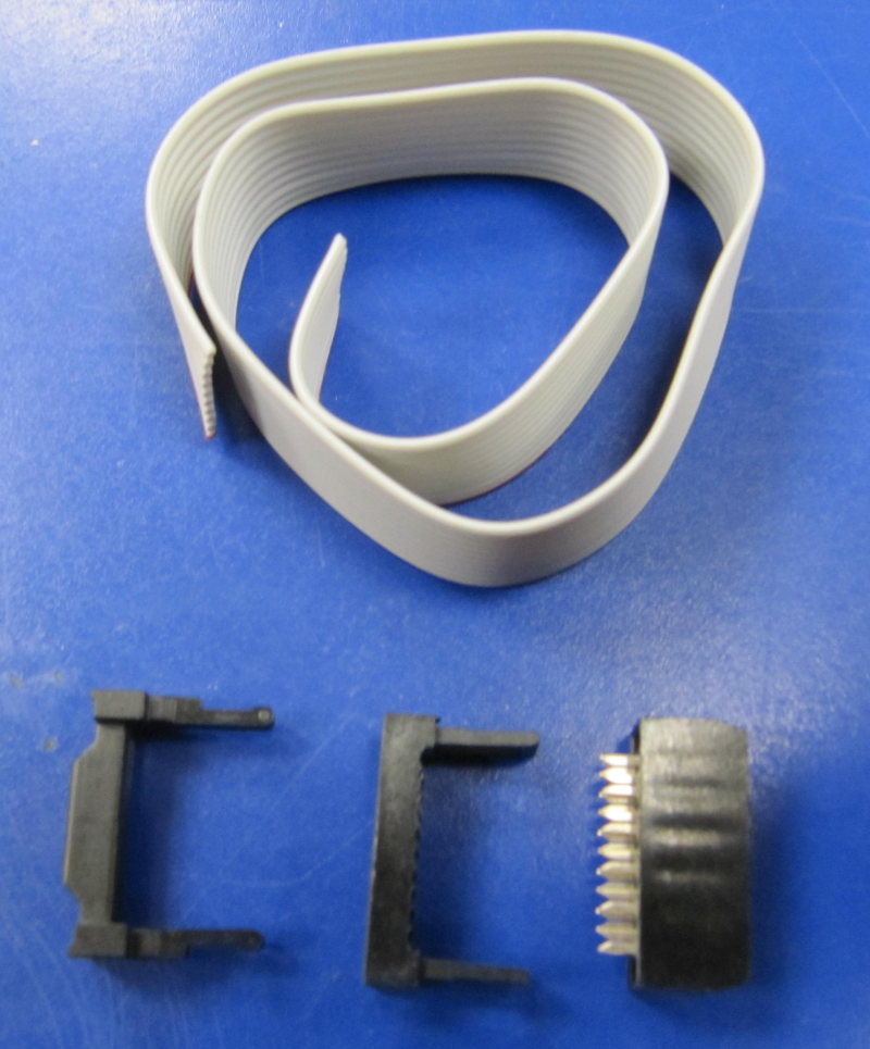
Further you have to connect the 4 pins.
TODO: add picture with circuit schematics of box header
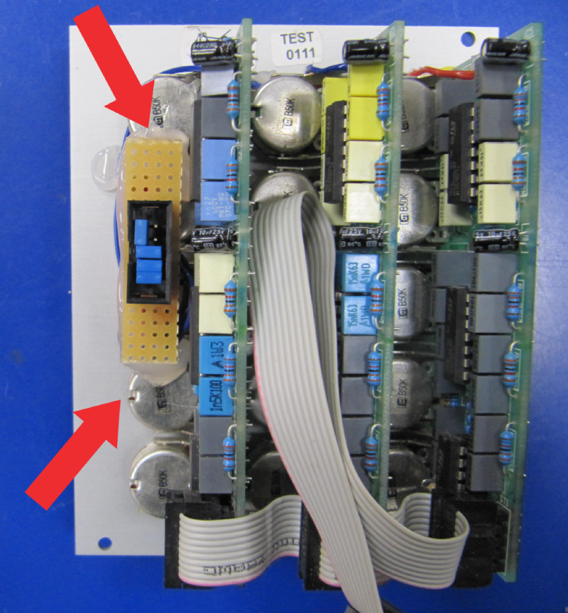
Hot glue is your friend - again
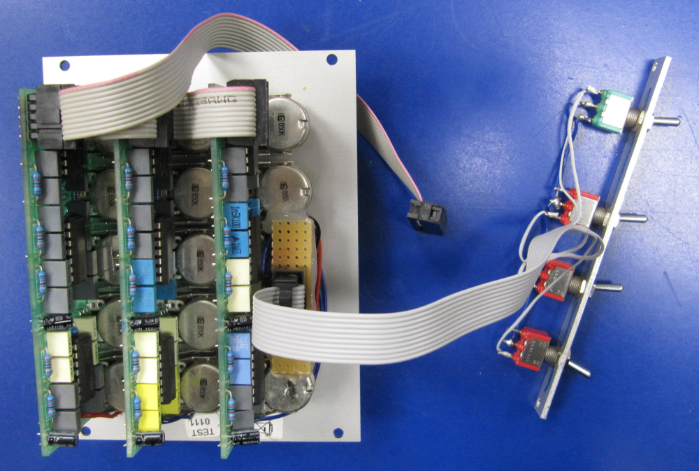
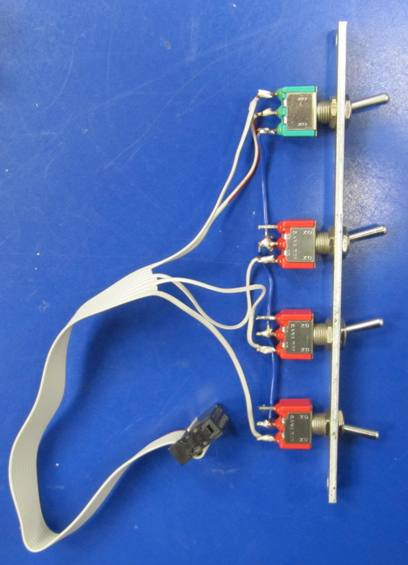
- Create a
2HPaluminium front panel128.5mmx9.8mmx2mmor use a blank panel Doepfer A-100 B2 - drill 4 holes for the switches
- mount the 4 switches
- solder the cables to the switches
TODO: add circuit schematics for the switches
Doepfer Filter Bank Bypass Breakout on modulargrid.net
see my other eurorack DIY projects